


3-8
Catalyst 3750-E and Catalyst 3560-E Switch Hardware Installation Guide
OL-9774-03
Chapter 3 Power Supply and Fan Module Installation
Installing a DC-Power Supply
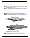
Installing the DC Power Supply in the Switch
To remove and install a DC-powered power-supply module, follow these steps:
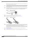
Step 1 Turn off power at the DC circuits. To ensure that power is removed from the DC circuits, locate the
circuit breakers for the DC circuits, switch the circuit breakers to the OFF position, and tape the
circuit-breaker switches in the OFF position.
Step 2 Use a number-2 Phillips screwdriver to remove the plastic safety cover from the power supply terminal
blocks.
Step 3 Use a number-1 Phillips screwdriver to remove the DC-input power wires from the power terminals.
Step 4 For 24- and 48-port switches, use a Phillips screwdriver to loosen the two captive screws at the lower
edge that secure the power-supply module to the switch chassis.
For Catalyst 3560E-12D and 3560E-12SD switches, use a Phillips screwdriver to loosen the captive
screw at the left edge of the power-supply module.
Step 5 Remove the power-supply module from the power slot by pulling on the extraction handle.
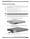
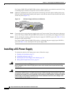
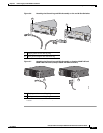
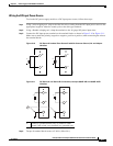
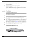
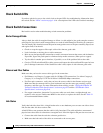
Step 6 Insert the new power supply into the power-supply slot, and gently push it into the slot (Figure 3-8 and
Figure 3-9). When correctly inserted, the power supply is flush with the switch rear panel.
Figure 3-8 Inserting the DC-Power Supply in 24- and 48-Port Switches
158123
FRU CC 265W
DC IN
PS OK
A
+
A
+
INPUT
-36 to -72V
/1
2A
OUTPUT
265W MAX
/22A
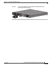
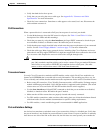
Figure 3-9 Inserting the DC-Power Supply in Catalyst 3560E-12D and 3560E-12SD Switches
(Catalyst 3560E-12D Switch Shown)
CONSOLE
Input
OK
Out
put
OK
202048
Step 7 For 24- and 48 port switches, align the two captive screws with the screw holes. Using a ratcheting
torque screwdriver, torque each screw to 7 lbf-in. (112 ozf-in.).
For Catalyst 3560E-12D and 3560E-12SD switches, align the captive screw with the screw hole. Using
a ratcheting torque screwdriver, torque the screw to 4 lbf-in. (64 ozf-in.)
Step 8 Connect the input power as described in the “Wiring the DC-Input Power Source” section.