


3-6
Catalyst 3750-E and Catalyst 3560-E Switch Hardware Installation Guide
OL-9774-03
Chapter 3 Power Supply and Fan Module Installation
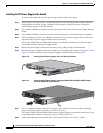
Installing a DC-Power Supply
Follow these steps to install either a single-ground lug or a dual-ground lug on the switch. Make sure to
follow any grounding requirements at your site.
Step 1 Locate the ground lug screw and the lug ring in the switch accessory kit. For a dual-ground connection,
locate the dual-ground adaptor (only 24- and 48-port switches) and dual-hole lug that ships with the
DC-power-supply module.
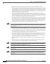
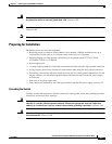
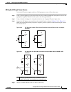
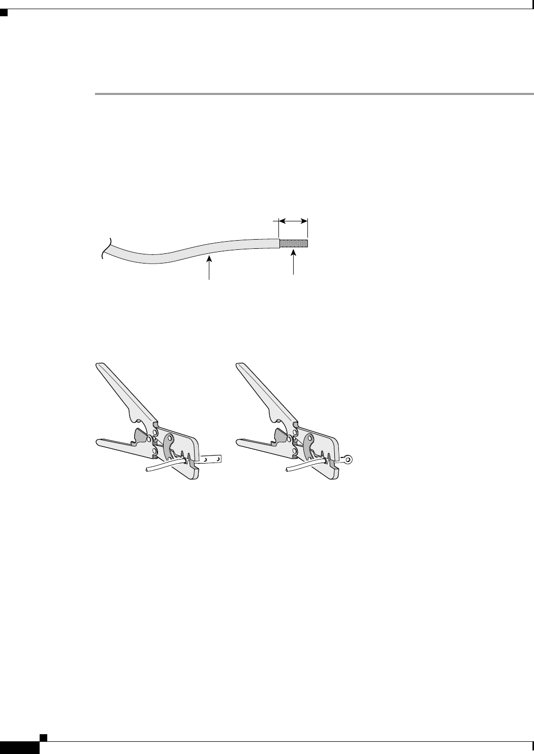
Step 2 If your ground wire is insulated, use a wire stripping tool to strip the 12-gauge or 6-gauge ground wire
to 0.5
inch (12.7 mm) ± 0.02 inch (0.5 mm) (Figure 3-4). Use 12-gauge copper ground wire for the
single-ground connection. Use 6-gauge copper ground wire for the dual-ground connection.
Figure 3-4 Stripping the Ground Wire
Insulation
Wire lead
0.5 in. (12.7 mm)
±
0.02 in. (0.5 mm)
60528
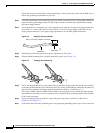
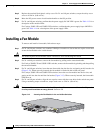
Step 3 Slide the open end of the ground lug over the exposed area of the wire.
Step 4 Using a Panduit crimping tool, crimp the ground lug to the wire (Figure 3-5).
Figure 3-5 Crimping the Ground Lug
200044
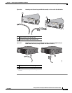
Step 5 For 24- and 48-port switches, use the ground screw to attach the single-ground lug and the wire assembly
or the dual-ground adaptor to the switch rear panel. For a dual-ground adaptor, attach the dual-hole lug
and the wire assembly to the adaptor with the supplied nuts (
Figure 3-6 and Figure 3-7).
For Catalyst 3560E-12D and 3560E-12SD switches, use the ground screw to attach the single-ground
lug and the wire assembly, or use two ground screws to attach the dual-ground lug and the wire assembly
to the switch rear panel.
Step 6 Using a ratcheting torque screwdriver, torque the ground-lug screws to 60 lbf-in. (960 ozf-in.)
(
Figure 3-6 and Figure 3-7).
Step 7 Connect the other end of the grounding wire to an appropriate grounding point at your site or to the rack.