


3-4
Catalyst 3750-E and Catalyst 3560-E Switch Hardware Installation Guide
OL-9774-03
Chapter 3 Power Supply and Fan Module Installation
Installing a DC-Power Supply
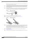
For Catalyst 3560E-12D and 3560E-12SD switches, align the captive screw with the screw hole. Using
a ratcheting torque screwdriver, torque the screw to 4
lbf-in. (64 ozf-in.)
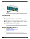
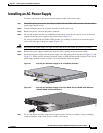
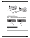
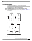
Step 8 (Optional) Assemble the AC power cord retainer with the large end of the plastic bushing facing away
from the switch. Position the assembly on the power cord, and insert the wire bales into the slots on the
switch rear panel (
Figure 3-3).
Figure 3-3 AC-Power Supply with Power Cord Retainer
157706
AC OK
PS OK
100-240 V
10-5 A
50-60 HZ
Step 9 Connect the power cord to the power supply and to an AC-power outlet. Turn on the power at the power
source. For Catalyst 3560E-12D and 3560E-12SD switches, also turn on the power supply on/off switch.
Step 10 For 24- and 48-port switches, confirm that the power supply AC OK LED is green. See Table 1-12 for a
description of the module LEDs.
For Catalyst 3560E-12D and 3560E-12SD switches, confirm that the power supply Input OK LED is
green. See
Table 1-14 for a description of the power supply LEDs.
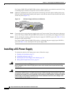
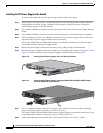
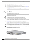
Installing a DC-Power Supply
To connect the switch to a DC-input power source, follow these steps:
1. Preparing for Installation, page 3-5
2. Grounding the Switch, page 3-5
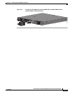
3. Installing the DC Power Supply in the Switch, page 3-8
4. Wiring the DC-Input Power Source, page 3-9
Warning
An exposed wire lead from a DC-input power source can conduct harmful levels of electricity. Be sure
that no exposed portion of the DC-input power source wire extends from the terminal block plug.
Statement 122
Warning
Before connecting or disconnecting ground or power wires to the chassis, ensure that power is
removed from the DC circuit. To ensure that all power is OFF, locate the circuit breaker on the panel
board that services the DC circuit, switch the circuit breaker to the OFF position, and tape the switch
handle of the circuit breaker in the OFF position. Use a voltmeter to test for 0 (zero) voltage at the
power terminals on the chassis.
Statement 196