


B-5
Catalyst 3750-E and Catalyst 3560-E Switch Hardware Installation Guide
OL-9774-03
Appendix B Connector and Cable Specifications
Cable and Adapter Specifications
Cable and Adapter Specifications
These sections describe the cables and adapters used with Catalyst 3750-E and Catalyst 3560-E
switches:
• 10-Gigabit Ethernet X2 Transceiver Module Cable Specifications, page B-5
• SFP Module Cable Specifications, page B-6
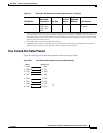
• Four Twisted-Pair Cable Pinouts, page B-7
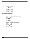
• Two Twisted-Pair Cable Pinouts, page B-8
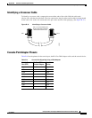
• Identifying a Crossover Cable, page B-9
• Console Port Adapter Pinouts, page B-9
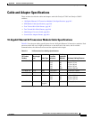
10-Gigabit Ethernet X2 Transceiver Module Cable Specifications
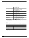
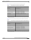
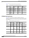
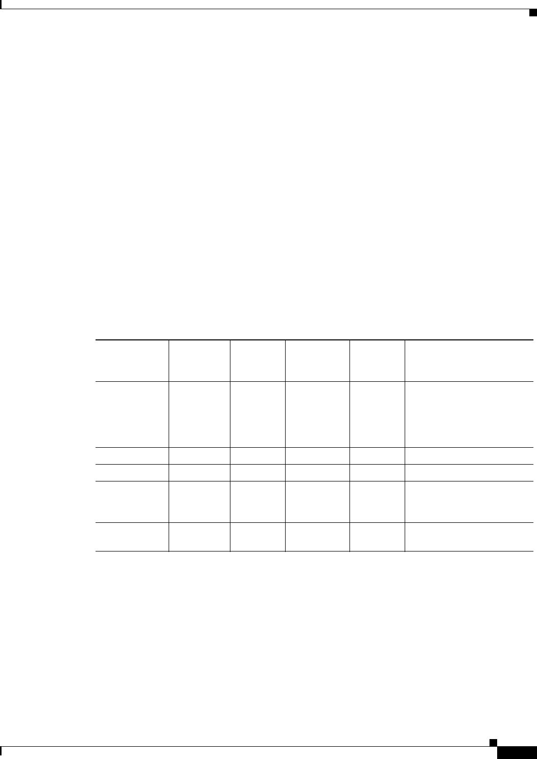
Table B-1 lists the port cabling specifications for the 10-Gigabit Ethernet X2 transceiver modules. Each
port must match the wave-length specifications on the other end of the cable, and for reliable
communications, the cable must not exceed the stipulated cable length.
Ta b l e B-1 X2 Transceiver Port Cabling Specifications
X2 Product
Number
Wavelength
(nm)
Cable Type
Core Size
(microns)
Modal
Bandwidth
(MHz/km)
Maximum Cabling Distance
X2-10GB-SR 850 MMF 62.5
62.5
50.0
50.0
50.0
160
200
400
500
2000
85 feet (26 m)
108 feet (33 m)
217 feet (66 m)
269 feet (82 m)
984 feet (300 m)
X2-10GB-LR 1310 SMF G.652 fiber — 32,810 feet (10 km)
X2-10GB-ER 1550 SMF G.652 fiber — 24.84 miles (40 km)
X2-10GB-LX4 1310
1. Mode conditioning patch cord is recommended for MMF applications.
MMF
1
62.5
50.0
50.0
500
400
500
984 feet (300 m)
787 feet (240 m)
984 feet (300 m)
X2-10GB-CX4 — InfiniBand
(copper)
— — 49 feet (15 m)