


3-7
Catalyst 3750-E and Catalyst 3560-E Switch Hardware Installation Guide
OL-9774-03
Chapter 3 Power Supply and Fan Module Installation
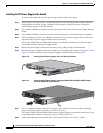
Installing a DC-Power Supply
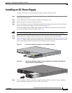
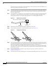
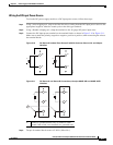
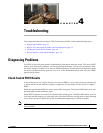
Figure 3-6 Attaching the Ground Lug and Wire Assembly on 24- and 48-Port Switches
FR
F
157547
1
2
1 Single-ground screw and lug ring
2 Dual-ground adaptor and dual-hole lug
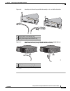
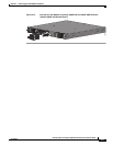
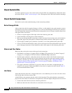
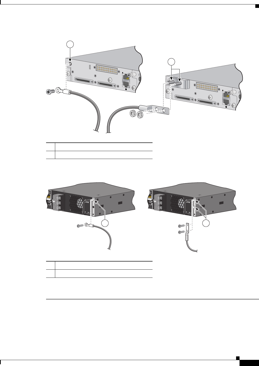
Figure 3-7 Attaching the Ground Lug and Wire Assembly on Catalyst 3560E-12D and
3560E-12SD Switches (Catalyst 3560E-12D Switch Shown)
202198
NSOLE
Input
OK
Output
OK
NSOLE
Input
OK
Output
OK
1 2
1 Single-ground screw and lug ring
1. See Figure 1-9 for the Catalyst 3560E-12SD ground
location.
1
2 Dual-ground screw and lug ring
1