


17
Installing a GRP
78-4339-09
Replacing a GRP
Step 7 Place the removed GRP on an antistatic mat or foam. If you plan to return the GRP to the factory,
immediately place it in an antistatic bag to prevent ESD damage.
Installing a GRP
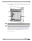
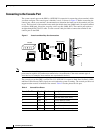
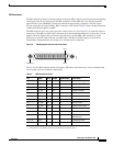
When you install a GRP, be sure to use the ejector levers, which help to ensure that the GRP is fully
inserted in the backplane connector. (See Figure 3.) When you simultaneously push the ejector levers
inward (toward the center of the GRP), the ejector levers push the GRP into the slot and ensure that the
GRP backplane connector is fully seated in the backplane.
Caution A GRP that is only partially connected to the backplane can halt the system.
Use the following procedure to install a GRP:
Step 1 Use an ESD-preventive wrist or ankle strap and follow its instructions for use.
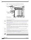
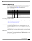
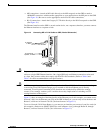
Step 2 Grasp the GRP faceplate with one hand and place your other hand under the carrier to support and
guide it into an upper card cage slot. (See Figure 4.)
Caution Avoid touching the GRP printed circuit board, components, or any edge connector pins.
Step 3 Place the bus-connector edge of the GRP in the appropriate slot and align the notches along the edge of
the carrier with the grooves at the top and bottom of the slot.
Step 4 While keeping the GRP edge connector parallel to the backplane, carefully slide the carrier into the slot
until the GRP faceplate makes contact with the ejector levers, then stop.
Step 5 Using the thumb and forefinger of each hand to pinch each ejector lever, simultaneously push both
ejectors toward the center of the GRP faceplate until they are perpendicular to the GRP faceplate.
(See Figure 4a.)
Step 6 Using a 3/16-inch flat-blade screwdriver, tighten the captive screws on the ends of the GRP. The captive
screws prevent the GRP from becoming partially dislodged from the backplane and ensure proper EMI
shielding. (These captive screws must be tightened to meet EMI specifications.)
Step 7 If you disconnected the console terminal to remove the GRP, or if you are installing a new GRP,
connect the console terminal to the console port. (See the “Connecting to the Console Port” section on
page 18.)
Step 8 Ensure that the console terminal is turned on.
Step 9 Turn on system power.
Step 10 Attach the network end of your RJ-45 or MII cable to your transceiver, switch, hub, repeater, DTE, or
other external equipment. Be sure to use the appropriate strain relief on cable connections.