


21
Connecting to the Ethernet Port
78-4339-09
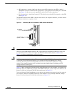
Replacing a GRP
MII Connections
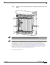
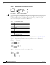
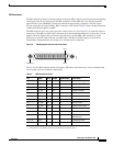
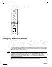
The MII connection requires an external physical sublayer (PHY) and an external transceiver. Depending
on the type of media you use between the MII connection on the GRP and your switch or hub, the
network side of your 100BASE-T transceiver should be appropriately equipped—with SC-type or
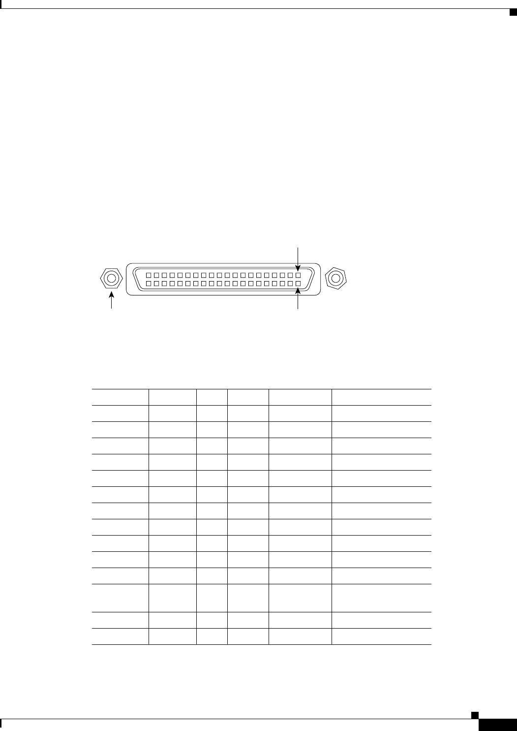
ST-type connectors (for optical fiber), BNC connectors, and so forth. Figure 9 shows the pin orientation
of the female MII receptacle on GRP.
The MII receptacle uses two screw-type locks, called jackscrews (see Figure 9), to secure the cable or
transceiver to the MII port. MII cables and transceivers have knurled thumbscrews (screws that you can
tighten with your fingers) that you fasten to the jackscrews on the GRP’s MII connector. Use the
jackscrews to provide strain relief for your MII cable. (The RJ-45 modular plug has strain relief
functionality incorporated into the design of its standard plastic connector.)
Figure 9 MII Receptacle (Horizontal Orientation)
Table 5 lists the MII connector pinout and signals. MII cables and transceivers are not available from
Cisco Systems, but are available commercially.
Jackscrew Pin 21
Pin 1
H6538
Table 5 MII Receptacle Pinout
Pin
1
1. Any pins not indicated are not used.
Signal Input Output Input/Output Description
14 to 17 TxD — Yes — Transmit Data
12 Tx_CLK Yes — — Transmit Clock
2
2. The signals Tx_CLK and Rx_CLK are generated by the external transceiver.
11 Tx_ER — Yes — Transmit Error
13 Tx_EN — Yes — Transmit Enable
3 MDC — Yes — MII Data Clock
4 to 7 RxD Yes — — Receive Data
9 Rx_CLK Yes — — Receive Clock
10 Rx_ER Yes — — Receive Error
8 Rx_DV Yes — — Receive Data Valid
18 COL Yes — — Collision
19 CRS Yes — — Carrier Sense
2 MDIO — — Yes MII Data
Input/Output
22 to 39 GND — — — Common ground
1, 20, 21, 40 V — — — +5.0 VDC