


49
Upgrading GRP Memory
78-4339-09
Implementing Additional Configuration and Maintenance Tasks
Change it to a value of 0x2102 (factory default) using the config-register 0x value command.
Step 13 Enter Ctrl-Z to exit configuration mode.
Step 14 Reboot the router and enable it using the recovered password.
Upgrading GRP Memory
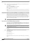
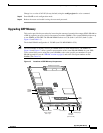
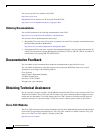
This section provides the procedure for increasing the amount of extended data output (EDO) DRAM on
a GRP by replacing up to two dual in-line memory modules (DIMMs). The system DRAM resides on up
to two DIMMs on the GRP. The DRAM DIMM sockets are U39 (bank 1) and U42 (bank 2). (See
Figure 15 and Table 14.)
The default DRAM configuration is 128 MB (one 128-MB DIMM in U39).
Note The total number of memory devices per DIMM differs for each manufacturer. The DIMMs in
Figure 16 and Figure 17 show a generic representation of the actual DRAM DIMMs for your GRP.
To be assured that you are using the correct DIMMs, refer to the specific part numbers for your
DRAM upgrade kit (see the “DRAM” section on page 6) and to the Cisco part numbers on the
DIMMs. (See Table 14.)
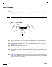
Figure 15 Locations of GRP Memory Components
Backplane connector
SLOT-0
GIGABIT ROUTE PROCESSOR
SLOT-1
COLL
LINK
TX
RX
RJ-45
MII
RESET
AUX
EJECT
H10547
Bank 2
DRAM DIMMs
Bank 1
PCMCIA slots
slot 0: bottom
slot 1: top
Console port
Ethernet
interface
(RJ-45 or MII)
Alphanumeric
LED displays
Auxiliary port
Flash
SIMM
U17
U42
U39