


2
Important Information
78-4339-09
Important Information
Important Information
This section contains information about the following hardware and software requirements:
• Router Information
• Cisco IOS Software Requirements
• Product Overview
Router Information
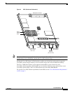
For hardware installation and maintenance information on Cisco 12000 Series Routers, refer to the
installation and configuration guide for your router. This includes information on card slot locations and
other general requirements.
Supported Platforms
The GRP operates on all Cisco 12000 series Internet Routers with the following requirements:
• Cisco 12016 and Cisco 12416—GRP plugs into slot 7 in the upper card cage. If the router is
equipped with an optional, redundant GRP, it must be installed in the far left slot of the lower card
cage (slot 8).
• Cisco 12410—GRP plugs into slot 9. If the router is equipped with an optional, redundant GRP, it
must be installed in slot 8.
• Cisco 12406—GRP plugs into any slot; however, slot 5 is recommended. If the router is equipped
with an optional, redundant GRP, it can be installed in any of the remaining five slots.
• Cisco 12404—GRP plugs into any of the five slots in the card cage, but slot 0 (zero) is the
recommended slot for the first GRP. If the router is equipped with an optional, redundant GRP, it
can be installed in any of the remaining slots.
• Cisco 12012—GRP plugs into slot 0 in the upper card cage. In a dual GRP system, the second GRP
is located in slot 11. This is the default factory configuration and is recommended to avoid heat-
related problems. The far right slot labeled Alarm card is reserved for the alarm card.
• Cisco 12008—GRP plugs into any slot in the upper card cage in the Cisco 12008 except the middle
two slots (which are reserved for the CSC cards and labeled CSC 0 and CSC 1).
GRP Redundancy
When two GRPs are installed in a Cisco 12000 Series Router, one GRP is the active GRP, and the other
is the backup, or standby GRP. If the active GRP fails or is removed from the system, the standby GRP
detects the failure and initiates a switchover. During a switchover, the standby GRP assumes control of
the router, connects with the network interfaces, and activates the local network management interface
and system console.
Note If your system includes redundant GRPs, both GRPs should have the same memory size. Redundancy
is not supported when using a GRP and a PRP in the same chassis. Cisco strongly recommends that
you avoid using mixed route processor cards to configure your router. Refer to the Route Processor
Redundancy Plus for the Cisco 12000 Series Internet Router publication for more information on
redundancy.