


24
GRP Boot Process Overview
78-4339-09
GRP Boot Process Overview
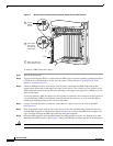
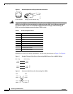
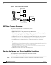
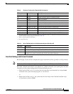
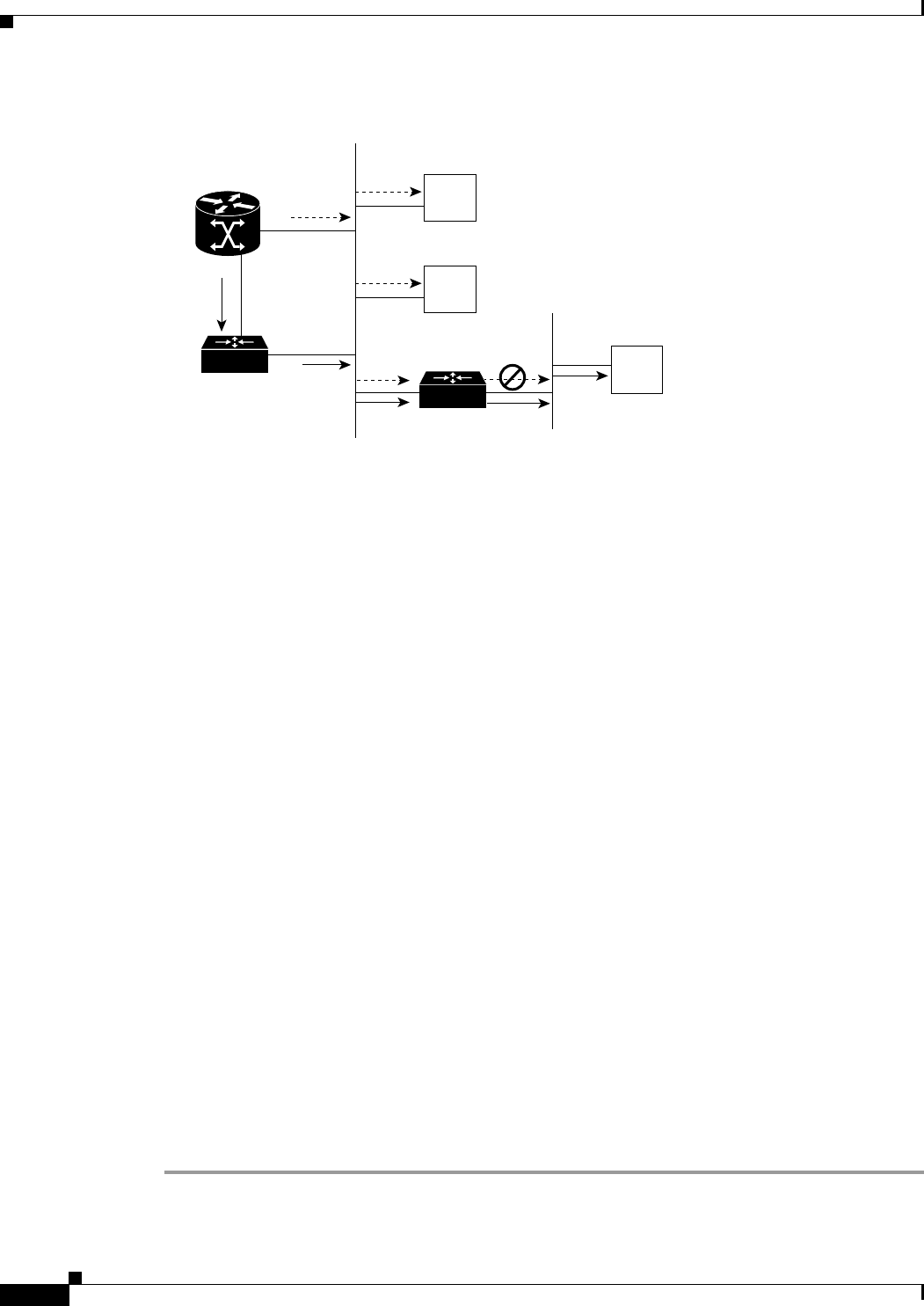
Figure 11 Using the Ethernet Port on the GRP
GRP Boot Process Overview
The following sequence describes a typical GRP boot process:
1. System power is turned on.
2. MBus module receives +5 VDC and starts executing MBus software.
3. GRP determines the system configuration by sending a message over the MBus requesting all
installed devices to identify themselves. The return response provides slot number, and card and
component type. The GRP, line cards, and CSCs are then powered up.
4. GRP power-on-reset logic delay, which allows power and both local and CSC clocks to stabilize.
5. After the power-on reset is released, the GRP begins to execute the ROM monitor software.
6. If the ROM monitor is configured to autoboot, it loads and boots the Cisco IOS software.
or
If the ROM monitor is not configured to autoboot, you must enter the appropriate b command at the
ROM monitor prompt (rommon>) to boot the Cisco IOS software.
7. When the Cisco IOS software boots, it polls all other cards in the system and powers them up,
loading their Cisco IOS software as needed.
8. GRP waits for all other cards to finish their boot processes.
Starting the System and Observing Initial Conditions
This section describes the initial system startup processes and procedures.
Use the following procedure to start your system:
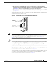
Step 1 Turn on each installed power supply by turning its system power switch to the on (|) position.
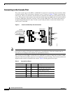
Router A
(Cisco 12000 series)
Router B
(Cisco 7500 series)
Router C
(Cisco 7500 series)
POS
EO
Host A
Network 1.0.0.0
EO
Host B
S6755
Host A
Network 2.0.0.0