


8
System Status LEDs
78-4339-09
Product Overview
System Status LEDs
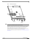
The two types of system status LEDs used on the GRP.
• Status LEDs
• Display LEDs
Status LEDs
The GRP has the following eight status LEDs:
• 2 PCMCIA activity LEDs (one LED per PCMCIA slot)—Each LED goes on when its PCMCIA slot
is accessed. The LEDs receive power from the switched slot voltage.
• 4 RJ-45 Ethernet port LEDs—These LEDs are used in conjunction with the RJ-45 Ethernet
connector. When the MII Ethernet port is in use, the LEDs are disabled. The LEDs indicate link
activity (LINK), collision detection (COLL), data transmission (TX), and data reception (RX).
• 2 RJ-45 or MII Ethernet port selection LEDs—These two LEDs, when on, identify which of the two
Ethernet connections you selected. When the RJ-45 port is selected, its LED is on, and the MII LED
is off. When the MII port is selected, its LED is on, and the RJ-45 LED is off.
Display LEDs
The alphanumeric display LEDs are organized as two rows of four characters each. The display content
is controlled by the MBus software of the GRP. Both rows of the display are powered by the MBus
module.
These alphanumeric display LEDs provide system status messages that are displayed during the boot
process and after the boot process is completed.
During the boot process, the display LEDs are controlled directly by the MBus. After the boot process,
they are controlled by the Cisco IOS software (via the MBus), and display messages designated by the
Cisco IOS software.
The LED displays indicate the following:
• Status of the GRP
• System error messages
• User-defined status/error messages
Soft Reset Switch
A soft reset switch provides a reset to the R5000 software on the GRP. You access the soft reset switch
through a small opening in the GRP faceplate. To depress the switch, insert a pape rclip or a similar
object into the opening.
Caution To prevent system problems or loss of data, use the soft reset switch only on the advice of Cisco
service personnel.