


25
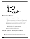
Starting the System and Observing Initial Conditions
78-4339-09
Starting the System and Observing Initial Conditions
For AC-input power supplies, the green AC OK LED should go on. For DC-input power supplies, the
green input OK LED should go on. For both types of power supplies, the output fail LED should be off.
Step 2 Listen for the system blower modules or fan trays in the router; you should immediately hear them
operating. In a noisy environment, place your hand in front of the exhaust vents to verify that the
blower modules are operating.
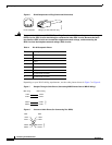
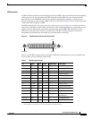
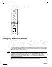
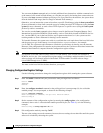
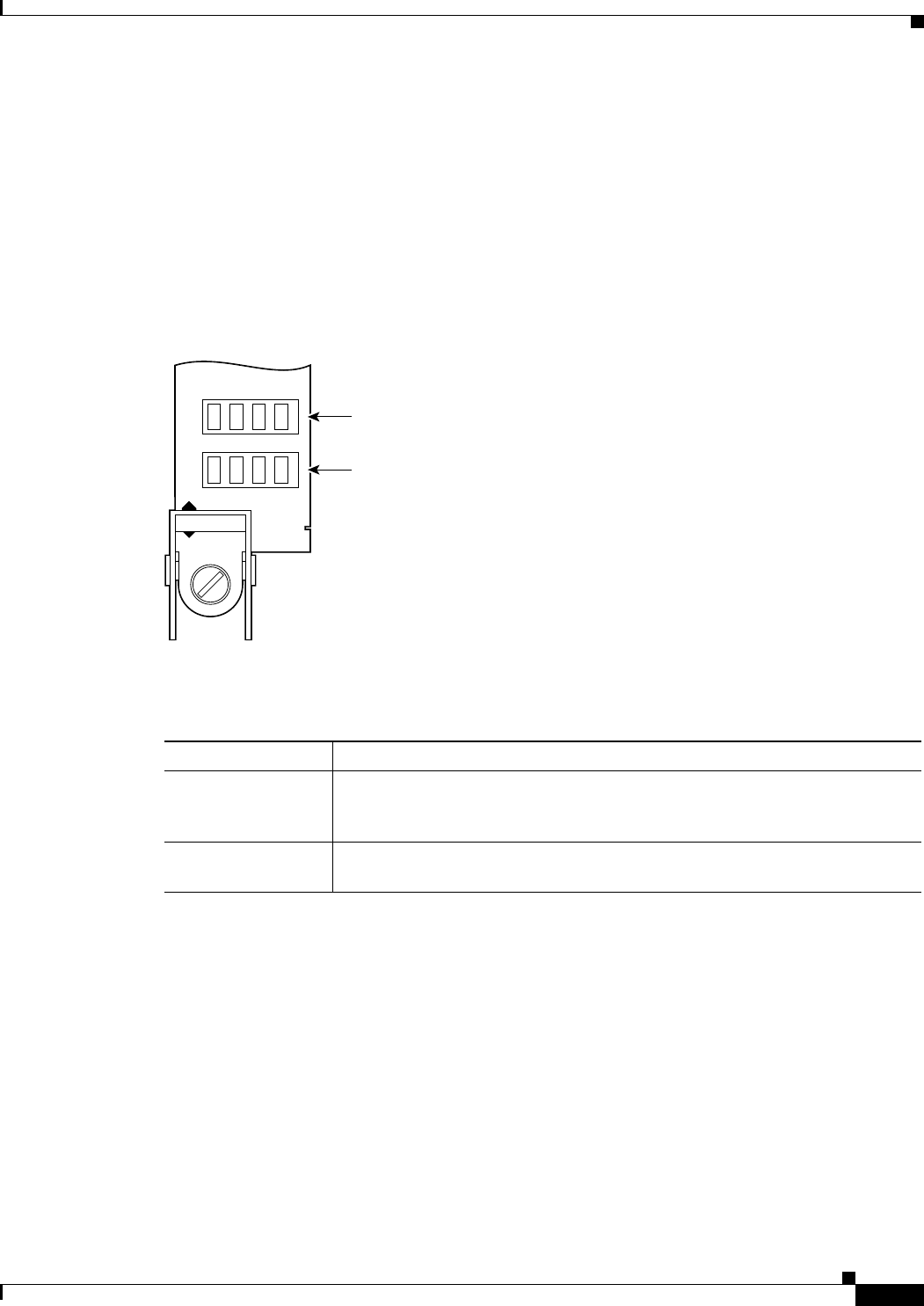
Step 3 During the GRP boot process, observe the GRP alphanumeric display LEDs, which are located at one
end of the GRP, near the ejector lever. (See Figure 12.)
The 4-digit displays show system messages and displays a sequence similar to that shown in Table 8.
Figure 12 GRP Alphanumeric Display LEDs (Front Panel View)
Table 8 GRP Alphanumeric Display LED Sequences
LED Display Description
MRAM
nnnn
GRP microcode loads into MBus random-access memory (RAM); where nnnn
is the microcode version. For example, Microcode Version 1.17 displays as
0117.
1
1. The version of microcode running on your GRP might be different.
MSTR
RP
This GRP is enabled and recognized by the system.
H10780
PROCESSOR
Upper alphanumeric
LED display (four digits)
Lower alphanumeric
LED display (four digits)