


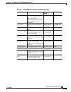

6-11
Cisco Provisioning Center User’s Guide
78-11339-01
Chapter 6 Configuring the Cisco NI-1 DLSAM Equipment Module
Working with Logical Ports
To re-upload you need to upload the fabric and Service elements for that node. For more information,
refer to the sections “Uploading the Fabric and Service Elements for a Node Object” and “Uploading the
Fabric Elements for a Node Object” in this chapter.
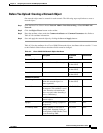
Working with Logical Ports
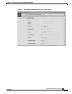
ATM logical ports can be created, modified, and deleted from DSL physical ports.
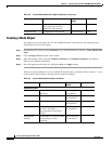
Creating Logical Ports
When creating a Cisco 6100/6130 ATM Logical Port, select an available DSL physical port (one whose
Interworking Model is set to None). This ensures that the selected physical port is not being used by
other network models. Ensure that the Maximum Connections field is set to 4 or less and update the other
fields (such as Name) as necessary. To create an ATM logical port, complete the following steps:
Step 1 From the Root Tree Viewer choose Network > Cisco NI1 DSLAM Network Name > Cisco NI1 DSLAM
Node > Node Name > Cisco NI1 DSLAM ATM Logical Port.
Step 2 Click the Object Viewer button on the toolbar.
Step 3 Fill in the attribute fields with the required values. Ensure that the Maximum Connections field is set
to four or less, and update other fields as necessary. You must select a physical port to which the logical
port belongs.
Step 4 Save and apply the network object by clicking the Save and Apply buttons.
Note You must use the copy and paste mechanism when entering a value for the physical port
that will contain the logical port. Manually entered physical port values are not supported.
Modifying Logical Ports
To modify an ATM logical port, complete the following steps:
Step 1 From the Root Tree Viewer choose Network > Cisco NI1 DSLAM Network Name > Cisco NI1 DSLAM
Node > Node Name > Cisco NI1 DSLAM ATM Logical Port > Logical Port name.
Step 2 Click the Object Viewer button on the toolbar.
Step 3 Click the field(s) containing the attribute you want to modify and enter a new value.
Step 4 Save and apply the network object by clicking the Save and Apply buttons.