


38-76
Catalyst 3750 Switch Software Configuration Guide
OL-8550-09
Chapter 38 Configuring IP Unicast Routing
Configuring Multi-VRF CE
The Catalyst 3750 switch supports multiple VPN routing/forwarding (multi-VRF) instances in customer
edge (CE) devices (multi-VRF CE) when the switch is running the IP services image. Multi-VRF CE
allows a service provider to support two or more VPNs with overlapping IP addresses. If you try to
configure it on a switch running the IP base image, you see an error message. On a switch running the
IP base image, configuring multi-VRF-CE and EIGRP stub routing at the same time is not allowed.
Note The switch does not use Multiprotocol Label Switching (MPLS) to support VPNs. For information about
MPLS VRF, refer to the Cisco IOS Switching Services Configuration Guide, Release 12.2 from the
Cisco.com page under Documentation > Cisco IOS Software > 12.2 Mainline > Command
References.
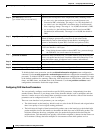
• Understanding Multi-VRF CE, page 38-76
• Default Multi-VRF CE Configuration, page 38-78
• Multi-VRF CE Configuration Guidelines, page 38-78
• Configuring VRFs, page 38-79
• Configuring VRF-Aware Services, page 38-81
• Configuring a VPN Routing Session, page 38-85
• Configuring BGP PE to CE Routing Sessions, page 38-85
• Multi-VRF CE Configuration Example, page 38-86
• Displaying Multi-VRF CE Status, page 38-90
Understanding Multi-VRF CE
Multi-VRF CE is a feature that allows a service provider to support two or more VPNs, where IP
addresses can be overlapped among the VPNs. Multi-VRF CE uses input interfaces to distinguish routes
for different VPNs and forms virtual packet-forwarding tables by associating one or more Layer 3
interfaces with each VRF. Interfaces in a VRF can be either physical, such as Ethernet ports, or logical,
such as VLAN SVIs, but an interface cannot belong to more than one VRF at any time.
Note Multi-VRF CE interfaces must be Layer 3 interfaces.
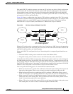
Multi-VRF CE includes these devices:
• Customer edge (CE) devices provide customers access to the service-provider network over a data
link to one or more provider edge routers. The CE device advertises the site’s local routes to the
router and learns the remote VPN routes from it. The Catalyst 3750 switch can be a CE.
• Provider edge (PE) routers exchange routing information with CE devices by using static routing or
a routing protocol such as BGP, RIPv2, OSPF, or EIGRP. The PE is only required to maintain VPN
routes for those VPNs to which it is directly attached, eliminating the need for the PE to maintain
all of the service-provider VPN routes. Each PE router maintains a VRF for each of its directly
connected sites. Multiple interfaces on a PE router can be associated with a single VRF if all of these
sites participate in the same VPN. Each VPN is mapped to a specified VRF. After learning local
VPN routes from CEs, a PE router exchanges VPN routing information with other PE routers by
using internal BGP (IBPG).
• Provider routers or core routers are any routers in the service provider network that do not attach to
CE devices.