


12-26
Catalyst 3750 Switch Software Configuration Guide
OL-8550-09
Chapter 12 Configuring Interface Characteristics
Configuring Layer 3 Interfaces
• Routed ports: Routed ports are physical ports configured to be in Layer 3 mode by using the no
switchport interface configuration command.
• Layer 3 EtherChannel ports: EtherChannel interfaces made up of routed ports.
EtherChannel port interfaces are described in Chapter 36, “Configuring EtherChannels and
Link-State Tracking.”
A Layer 3 switch can have an IP address assigned to each routed port and SVI.
There is no defined limit to the number of SVIs and routed ports that can be configured in a switch stack.
However, the interrelationship between the number of SVIs and routed ports and the number of other
features being configured might have an impact on CPU usage because of hardware limitations. If the
switch is using maximum hardware resources, attempts to create a routed port or SVI have these results:
• If you try to create a new routed port, the switch generates a message that there are not enough
resources to convert the interface to a routed port, and the interface remains as a switchport.
• If you try to create an extended-range VLAN, an error message is generated, and the extended-range
VLAN is rejected.
• If the switch is notified by VLAN Trunking Protocol (VTP) of a new VLAN, it sends a message that
there are not enough hardware resources available and shuts down the VLAN. The output of the
show vlan user EXEC command shows the VLAN in a suspended state.
• If the switch attempts to boot up with a configuration that has more VLANs and routed ports than
hardware can support, the VLANs are created, but the routed ports are shut down, and the switch
sends a message that this was due to insufficient hardware resources.
All Layer 3 interfaces require an IP address to route traffic. This procedure shows how to configure an
interface as a Layer 3 interface and how to assign an IP address to an interface.
Note If the physical port is in Layer 2 mode (the default), you must enter the no switchport interface
configuration command to put the interface into Layer 3 mode. Entering a no switchport command
disables and then re-enables the interface, which might generate messages on the device to which the
interface is connected. Furthermore, when you put an interface that is in Layer 2 mode into Layer 3
mode, the previous configuration information related to the affected interface might be lost, and the
interface is returned to its default configuration.
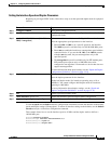
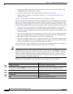
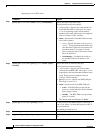
Beginning in privileged EXEC mode, follow these steps to configure a Layer 3 interface:
Command Purpose
Step 1
configure terminal Enter global configuration mode.
Step 2
interface {{fastethernet | gigabitethernet} interface-id}
| {vlan vlan-id} | {port-channel port-channel-number}
Specify the interface to be configured as a Layer 3
interface, and enter interface configuration mode.
Step 3
no switchport For physical ports only, enter Layer 3 mode.
Step 4
ip address ip_address subnet_mask Configure the IP address and IP subnet.
Step 5
no shutdown Enable the interface.
Step 6
end Return to privileged EXEC mode.