


38-86
Catalyst 3750 Switch Software Configuration Guide
OL-8550-09
Chapter 38 Configuring IP Unicast Routing
Configuring Multi-VRF CE
Use the no router bgp autonomous-system-number global configuration command to delete the BGP
routing process. Use the command with keywords to delete routing characteristics.
Multi-VRF CE Configuration Example
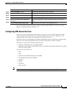
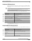
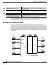
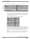
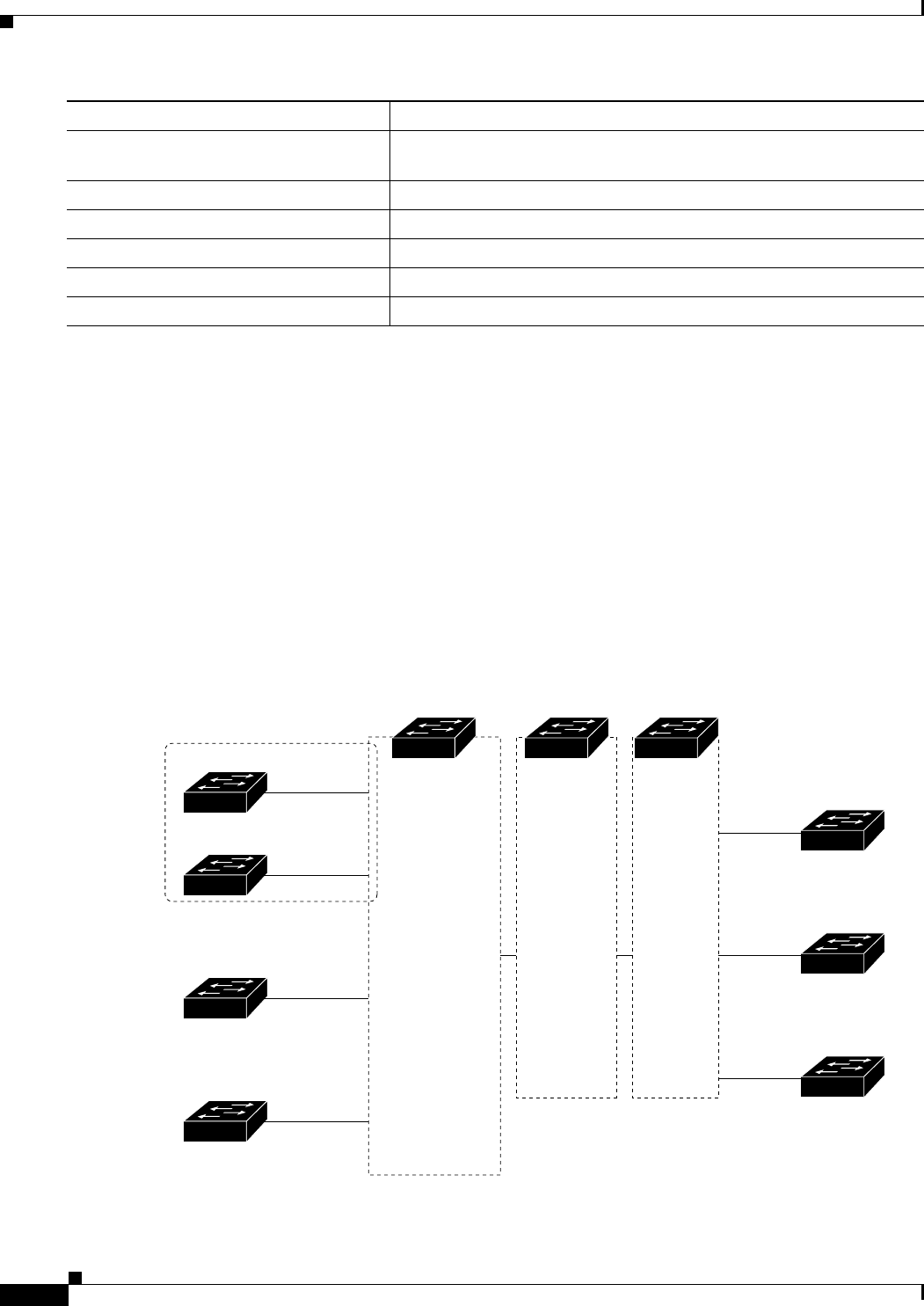
Figure 38-7 is a simplified example of the physical connections in a network similar to that in
Figure 38-6. OSPF is the protocol used in VPN1, VPN2, and the global network. BGP is used in the CE
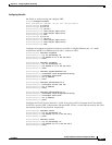
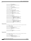
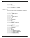
to PE connections. The examples following the illustration show how to configure a Catalyst 3750 switch
as CE Switch A, and the VRF configuration for customer switches D and F. Commands for configuring
CE Switch C and the other customer switches are not included but would be similar. The example also
includes commands for configuring traffic to Switch A for a Catalyst 6000 or Catalyst 6500 switch acting
as a PE router.
Figure 38-7 Multi-VRF CE Configuration Example
Step 6
address-family ipv4 vrf vrf-name Define BGP parameters for PE to CE routing sessions, and enter VRF
address-family mode.
Step 7
neighbor address remote-as as-number Define a BGP session between PE and CE routers.
Step 8
neighbor address activate Activate the advertisement of the IPv4 address family.
Step 9
end Return to privileged EXEC mode.
Step 10
show ip bgp [ipv4] [neighbors] Verify BGP configuration.
Step 11
copy running-config startup-config (Optional) Save your entries in the configuration file.
Command Purpose
Switch A
Switch D
VPN1
VPN2
CE1
Global network
208.0.0.0
Fast
Ethernet
8
Gigabit
Ethernet
1
101386
PE CE2
Switch E
108.0.0.0
Fast
Ethernet
7
Switch F
118.0.0.0
Fast
Ethernet
11
Switch G
168.0.0.0
Fast
Ethernet
3
VPN1
VPN2
Global network
Switch H
Switch J
Switch K
CE = Customer-edge device
PE = Provider-edge device
Switch B Switch C