


22-12
Catalyst 3750 Switch Software Configuration Guide
OL-8550-09
Chapter 22 Configuring DHCP Features and IP Source Guard Features
Configuring DHCP Snooping
To disable the DHCP server and relay agent, use the no service dhcp global configuration command.
See the “Configuring DHCP” section of the “IP Addressing and Services” section of the Cisco IOS IP
Configuration Guide, Release 12.2 from the Cisco.com page under Documentation > Cisco IOS
Software > 12.2 Mainline > Configuration Guides for these procedures:
• Checking (validating) the relay agent information
• Configuring the relay agent forwarding policy
Specifying the Packet Forwarding Address
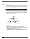
If the DHCP server and the DHCP clients are on different networks or subnets, you must configure the
switch with the ip helper-address address interface configuration command. The general rule is to
configure the command on the Layer 3 interface closest to the client. The address used in the ip
helper-address command can be a specific DHCP server IP address, or it can be the network address if
other DHCP servers are on the destination network segment. Using the network address enables any
DHCP server to respond to requests.
Beginning in privileged EXEC mode, follow these steps to specify the packet forwarding address:
Command Purpose
Step 1
configure terminal Enter global configuration mode.
Step 2
interface vlan vlan-id Create a switch virtual interface by entering a VLAN
ID, and enter interface configuration mode.
Step 3
ip address ip-address subnet-mask Configure the interface with an IP address and an IP
subnet.
Step 4
ip helper-address address Specify the DHCP packet forwarding address.
The helper address can be a specific DHCP server
address, or it can be the network address if other
DHCP servers are on the destination network
segment. Using the network address enables other
servers to respond to DHCP requests.
If you have multiple servers, you can configure one
helper address for each server.
Step 5
exit Return to global configuration mode.
Step 6
interface range port-range
or
interface interface-id
Configure multiple physical ports that are connected
to the DHCP clients, and enter interface range
configuration mode.
or
Configure a single physical port that is connected to
the DHCP client, and enter interface configuration
mode.
Step 7
switchport mode access Define the VLAN membership mode for the port.
Step 8
switchport access vlan vlan-id Assign the ports to the same VLAN as configured in
Step 2.
Step 9
end Return to privileged EXEC mode.