


VIP-4R/4T Installation and Configuration 11
Versatile Interface Processor Functions
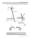
Caution To prevent system problems, do not remove port adapters from the VIP motherboard or
attempt to install other port adapters on the VIP motherboard.
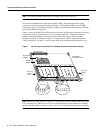
VIP Microcode Overview
The VIP microcode (firmware) is an image that provides card-specific software instructions. A Flash
memory device in socket U17 of the VIP contains the default microcode boot image. The router
supports downloadable microcode, which enables you to upgrade microcode versions by
downloading new microcode images, storing them in system Flash memory, and instructing the
system to load its image from Flash instead of the default VIP image. (The RP in the Cisco 7000 and
7010 loads software from ROM or Flash memory; the RSP loads software from Flash only.) You can
store multiple images for an interface type and, with a configuration command, instruct the system
to load any one of them or the default ROM image. All interfaces of the same type (VIP, and so on)
will load the same microcode image, either from the default ROM image or from a single image
stored in system Flash. Although multiple microcode versions for a specific interface type can be
stored concurrently in Flash, only one image can load at startup. The show controllers cbus
command displays the currently loaded and running microcode version for the SP or SSP (in the
Cisco 7000 series routers), each interface processor, and VIP. The show startup-config EXEC
command shows the current system instructions for loading microcode at startup.
Software and interface processor microcode images are carefully optimized and bundled to work
together. Overriding the bundle can result in system incompatibilities. We recommend that you use
the microcode included in the software bundle. For a complete description of microcode and
downloading procedures, refer to the section “Upgrading VIP Microcode” on page 23.
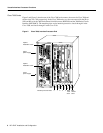
VIP Installation Prerequisites
This section provides a list of parts and tools you will need to perform the VIP installation, and it
also includes safety and ESD-prevention guidelines to help you avoid injury and damage to the
equipment. This section also provides a detailed description of the OIR function to help you perform
online installation successfully and avoid error message and system restarts. If you are installing a
new VIP, be sure to review the equipment descriptions and distance limitations in the port adapter
sections “Serial Distance Limitations” and “Token Ring Distance Limitations” when preparing your
site and planning network connections.
List of Parts and Tools
You need the following tools and parts to install or upgrade a VIP. If you need additional equipment,
contact a service representative for ordering information.
• Cables appropriate for the port adapter interfaces on your VIP
• Number 1 Phillips and a 3/16-inch, flat-blade screwdriver
• Your own ESD-prevention equipment or the disposable grounding wrist strap included with all
upgrade kits, FRUs, and spares