


VIP-4R/4T Installation and Configuration 13
Versatile Interface Processor Functions
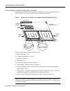
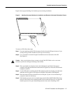
• Handle carriers by the handles and carrier edges only; avoid touching the board or connectors.
• Place a removed processor module board-side-up on an antistatic surface or in a static shielding
bag. If you plan to return the component to the factory, immediately place it in a static shielding
bag.
• Avoid contact between the processormodule and clothing. The wrist strap only protects the board
from ESD voltages on the body; ESD voltages on clothing can still cause damage.
• Never attempt to remove the printed circuit board from the metal interface processor carrier.
Caution For safety, periodically check the resistance value of the antistatic strap. The
measurement should be between 1 and 10 megohms.
Online Insertion and Removal—An Overview
The OIR feature allows you to remove and replace a VIP board while the system is operating; you
do not need to notify the software or shut down the system power.
Note The VIP port adapters themselves do not support OIR, nor are they FRUs.
This section describes mechanical functions of system components, emphasizes the importance of
following correct procedures to avoid unnecessary board failures, and is for background only;
specific VIP procedures follow in the section “VIP Installation” on page 16.
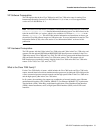
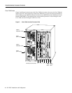
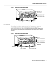
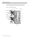
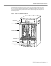
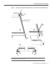
Each interface processor contains a receptacle with which it connects to the system backplane. Each
backplane connector comprises a set of tiered pins, in three lengths. The pins send specific signals
to the system as they make contact with the card. The system assesses the signals it receives and the
order in which it receives them to determine what event is occurring and what task it needs to
perform, such as reinitializing new interfaces or shutting down removed ones.
For example, when inserting an interface processor, the longest pins make contact with the
backplane first, and the shortest pins make contact last. The system recognizes the signals and the
sequence in which it receives them. The system expects to receive signals from the individual pins
in this logical sequence, and the ejector levers help to ensure that the pins mate in this sequence.
When you remove or insert an interface processor, the backplane pins send signals to notify the
system, which then performs as follows:
1 Rapidly scans the backplane for configuration changes and does not reset any interfaces.
2 Initializes all newly inserted interface processors, noting any removed interfaces and placing
them in the administratively shut down state.
3 Brings all previously configured interfaces on the interface processor back to the state they were
in when they were removed. Any newly inserted interfaces are put in the administratively shut
down state, as if they were present (but unconfigured) at boot time. If a similar interface processor
type has been reinserted into a slot, then its ports are configured and brought on line up to the
port count of the original interface processor.