


VIP-4R/4T Installation and Configuration 61
VIP Port Adapter Functions
Interface ports on the 4T port adapter maintain the same address regardless of whether other
interface processors are installed or removed. However, when you move a VIP to a different slot, the
first number in the address changes to reflect the new slot number.
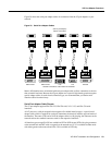
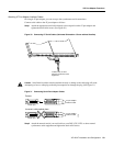
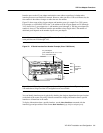
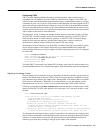
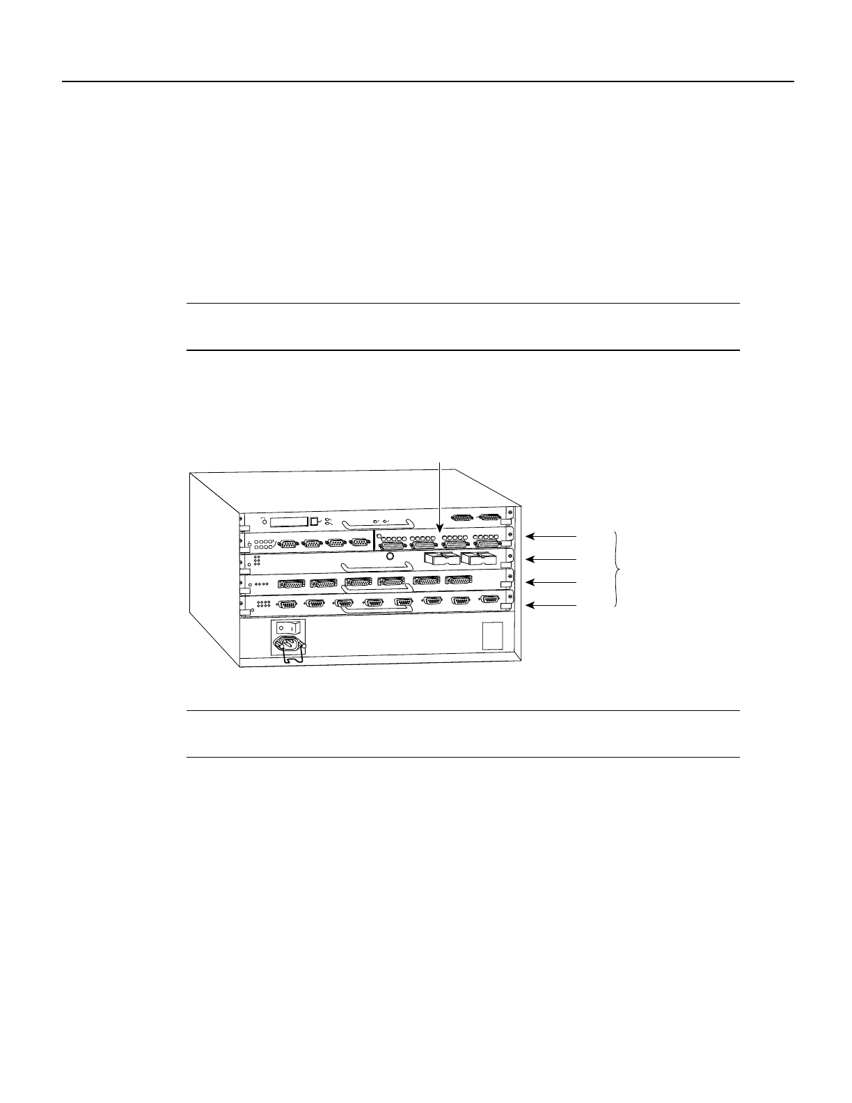
Figure 32 shows some of the slot port adapter and interface ports of a sample Cisco 7505 system.
For example, on a VIP-4R/4T VIP in slot 3, the addresses of the 4T port adapter are 3/1/0 through
3/1/3 (chassis slot 3, port adapter slot 1, and interface ports 0 through 3). The first port adapter slot
number is always 0. The individual interface port numbers always begin with 0. The number of
additional ports depends on the number of ports on a port adapter.
Note If you remove the 4T-equipped VIP from slot 3 and install it in slot 2, the addresses of those
same ports become 2/1/0 through 2/1/3.
Figure 32 4T Serial Interface Port Number Example (Cisco 7505 Shown)
Note Current VIP configurations support only one 4R port adapter and one 4T port adapter on a
VIP motherboard. Single and dual 4T configurations are not available.
You can identify interface ports by physically checking the slot/port adapter/interface port location
on the back of the router or by using software commands to display information about a specific
interface or all interfaces in the router.
To display information about a specific interface, use the show interfaces command with the
interface type and port address in the format show interfaces [type slot/port adapter/port].
H5989
Slot 0
Slot 1
Slot 2
Slot 3
Interface
processor
slots
EJECT
SLOT 0
SLOT 1
NORMAL
CPU HALT
RESET
CONSOLE
ROUTE SWITCH PROCESSOR
FAST SERIAL
4/T port adapter
(port numbers 3/1/0, 3/1/1, 3/1/2,
3/1/3, from left to right)
CD
LB
RC
RD
TC
TD
CD
LB
RC
RD
TC
TD
CD
LB
RC
RD
TC
TD
CD
LB
RC
RD
TC
TD
TD
ENAB
IN USE
4/16 MB
2
2
1
2
0
3