


VIP-4R/4T Installation and Configuration 7
Versatile Interface Processor Functions
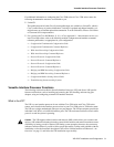
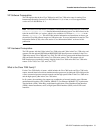
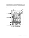
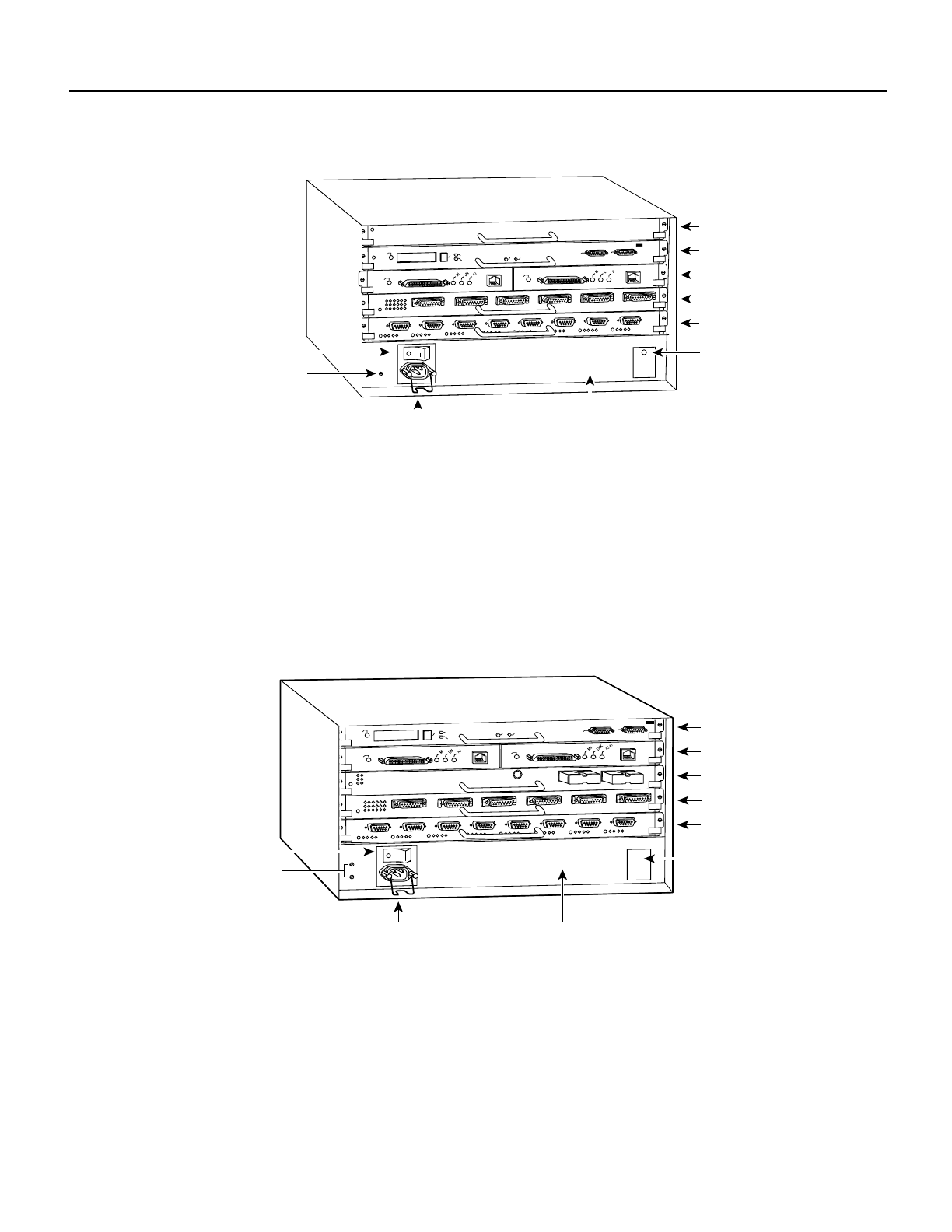
Figure 3 Cisco 7010, Interface Processor End
Cisco 7500 Series
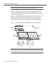
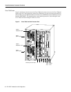
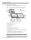
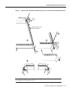
Figure 4, Figure 5, and Figure 6 show the rear of the Cisco 7500 series routers: the five-slot
Cisco 7505, the seven-slot Cisco 7507, and the thirteen-slot Cisco 7513, respectively.
In the Cisco 7505, one slot (4) is reserved for the Route Switch Processor (RSP1), which contains
the system processor and performs packet switching functions. Slots 0 through 3 are for interface
processors.
Figure 4 Cisco 7505, Interface Processor End
H5874
RSP7000CI slot 4
RSP7000 slot 3
Interface processor slot 1
DC OK LED
Power switch
Chassis ground
screw
Power receptacle
Interface processor slot 2
Interface processor slot 0
AC-input power supply
EJECT
SLOT 0
SLOT 1
NORMAL
CPU HALT
RESET
AUX.
CONSOLE
ROUTE SWITCH PROCESSOR
ENABLE
ENABLE
H2761
RSP slot
DC OK LED
o
wer switch
Chassis
grounding
receptacles
Power receptacle AC-input power supply
EJECT
SLOT 0
SLOT 1
NORMAL
CPU HALT
RESET
AUX.
CONSOLE
ROUTE SWITCH PROCESSOR
ENABLE
ENABLE
Interface processor slot 1
Interface processor slot 2
Interface processor slot 0
Interface processor slot 3