


20 VIP-4R/4T Installation and Configuration
Versatile Interface Processor Functions
The following example display shows the events logged by the system as a new VIP is inserted in
slot 3. (Serial interfaces are used in the following examples.)
Router#
%OIR-6-INSCARD: Card inserted in slot 3, interfaces administratively shut down
%LINK-5-CHANGED: Interface Serial3/1/0, changed state to administratively down
%LINK-5-CHANGED: Interface Serial3/1/1, changed state to administratively down
Verify that the VIP is installed correctly as follows:
Step 1 While the system reinitializes each interface, observe the console display messages and
verify that the system discovers the VIP as follows:
• If you installed a new VIP, the system should recognize all new interfaces but leave them
configured as down.
• If you replaced a VIP, the system should recognize each interface and place it in the
same state (up or down) each was in when you removed the VIP.
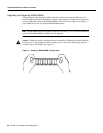
Step 2 When the reinitialization is complete, verify that the enabled LED on each port adapter
goes on and remains on. If it does, proceed to step 5. If it does not, proceed to the next step.
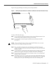
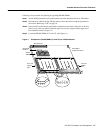
Step 3 If the enabled LED on a port adapter fails to go on, suspect that the VIP board connector is
not fully seated in the backplane. Loosen the captive installation screws, then firmly push
both ejector levers into place until they are approximately in the same orientation as the VIP
faceplate. Tighten the captive installation screws. After the system reinitializes the
interfaces, the enabled LED on the port adapter should go on. If it does, proceed to Step 5.
If it does not, proceed to Step 4.
Step 4 If the enabled LED still fails to go on, remove the VIP and try installing it in another
available interface processor slot.
• If the enabled LED goes on when the VIP is installed in the new slot, suspect a failed
backplane port in the original interface processor slot.
• If the enabled LED still fails to go on, but other LEDs on the VIP go on to indicate
activity, proceed to Step 5 to resume the installation checkout and suspect that the
enabled LED on the port adapter has failed.
• If no LEDs on the VIP go on, suspect that the VIP is faulty.
• If the enabled LED still does not go on, do not proceed with the installation. Contact a
service representative to report the problem and obtain further instructions.
Step 5 If the VIP is new and not a replacement, you have to configure the new interfaces. Proceed
to the appropriate configuration section for your port adapter. (This does not have to be
done immediately, but new interfaces will not be available until you configure them.)
Step 6 If the VIP is a replacement, use the show interfaces type slot/port adapter/port or show
controllers cbus command to verify the status of the interfaces. (Refer to the section
“Verifying VIP Status Using show Commands” on page 21.)
If you replaced a VIP with a new VIP with a greater number of ports (for example, if you
replaced a one-port VIP with a two-port VIP), the system will recognize the first interface,
but will not recognize the additional interface. The new interface will remain in the
shutdown state until you configure it.
Step 7 When the interfaces are up, check the activity of each interface by observing the status
LEDs, which are described in the appropriate LED section for your port adapter type.
Step 8 In general, if an interface’s LED fails to go on and a cable is connected to the port, check
the cable connection and make certain it is properly seated in the connector.