


60 VIP-4R/4T Installation and Configuration
VIP Port Adapter Functions
Configuring the 4T Interfaces
If you installed a new VIP or if you want to change the configuration of an existing interface, you
must enter Configuration mode to configure the new interfaces. If you replaced a VIP that was
previously configured, the system will recognize the new 4T port adapter interfaces and bring each
of them up in their existing configuration.
After you verify that the new 4T port adapter is installed correctly (the enabled LED goes on), use
the privileged-level configure command to configure the new interfaces. Be prepared with the
information you will need, such as the following:
• Protocols you plan to route on each new interface
• Internet protocol (IP) addresses if you will configure the interfaces for IP routing
• Whether or not the new interfaces will use bridging
• Timing source for each new interface and clock speeds for external timing
Refer to the appropriate software documentation for descriptions of the configuration options
available and instructions for configuring a serial interface.
The following sections describe the commands for configuring an external clock signal for a DCE
interface and for configuring a port for NRZI encoding or 32-bit CRC. Configuration commands are
executed from the privileged level of the EXEC command interpreter, which usually requires
password access. (See the section “Using the EXEC Command Interpreter” on page 69.) Refer to
the description that follows and contact your system administrator, if necessary, to obtain access.
Selecting Chassis Slot, Port Adapter, and Serial Interface Port Numbers
The following section describes how to identify chassis slot, port adapter, and serial interface port
numbers.
Note Although the processor slots in the seven-slot Cisco 7000 and 13-slot Cisco 7513 are
vertically oriented and those in the five-slot Cisco 7010 and Cisco 7505 are horizontally oriented, all
models use the same method for slot and port numbering. (For interface processor slot orientation in
your chassis, refer to Figure 2, Figure 3, Figure 4, Figure 5, or Figure 6.)
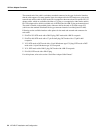
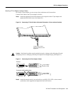
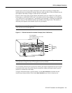
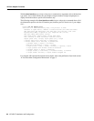
In the router, physical port addresses specify the actual physical location of each interface port on
the router interface processor end. (See Figure 32.) This address is composed of a three-part number
in the format chassis slot number/port adapter number/interface port number.
The first number identifies the chassis slot in which the VIP is installed (as shown in the example
system in Figure 32). The second number identifies the physical port adapter number on the VIP, and
is either 0 or 1. The interface ports on each 4T port adapter are always numbered in sequence as
interface 0 through 3.