


54 VIP-4R/4T Installation and Configuration
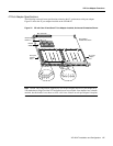
VIP Port Adapter Functions
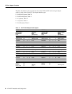
The tables that follow list the signal pinouts for both the DTE and DCE mode serial port adapter
cables, for each of the following 4T port adapter interface types:
• EIA/TIA-232 pinout, Table 10
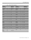
• EIA/TIA-449 pinout, Table 11
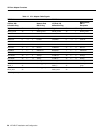
• X.21 pinout, Table 12
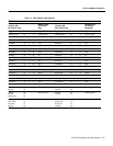
• V.35 pinout, Table 13
• EIA-530 pinout, Table 14
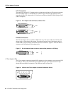
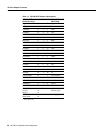
Table 10 EIA/TIA-232 Adapter Cable Signals
DTE Cable DCE Cable
VIP End, HD
1
60-Position
Plug
1. HD = high density.
Network
End,
DB-25 Plug
VIP End, HD
60-Position
Plug
Network End,
DB-25
Receptacle
Signal Pin Pin Signal Signal Pin Pin Signal
Shield ground 46 1 Shield ground Shield ground 46 1 Shield ground
TxD/RxD 41 —> 2 TxD RxD/TxD 36 <— 2 TxD
RxD/TxD 36 <— 3 RxD TxD/RxD 41 —> 3 RxD
RTS/CTS 42 —> 4 RTS CTS/RTS 35 <— 4 RTS
CTS/RTS 35 <— 5 CTS RTS/CTS 42 —> 5 CTS
DSR/DTR 34 <— 6 DSR DTR/DSR 43 —> 6 DSR
Circuit ground 45 7 Circuit ground Circuit ground 45 7 Circuit ground
DCD/LL 33 <— 8 DCD LL/DCD 44 —> 8 DCD
TxC/NIL 37 <— 15 TxC TxCE/TxC 39 —> 15 TxC
RxC/TxCE 38 <— 17 RxC NIL/RxC 40 —> 17 RxC
LL/DCD 44 —> 18 LTST DCD/LL 33 <— 18 LTST
DTR/DSR 43 —> 20 DTR DSR/DTR 34 <— 20 DTR
TxCE/TxC 39 —> 24 TxCE RxC/TxCE 38 <— 24 TxCE
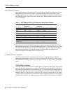
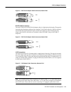
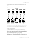
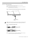
Mode 0
Ground
Mode_DCE
50
51
52
Shorting
group
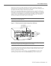
Mode 0
Ground
50
51 Shorting group