


VIP-4R/4T Installation and Configuration 51
VIP Port Adapter Functions
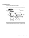
Note The VIP is oriented horizontally in the Cisco 7010 and Cisco 7505, and vertically in the Cisco
7000, the Cisco 7507, and the Cisco 7513.
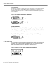
The following conditions must be met before the enabled LED goes on:
• The 4T interface is correctly connected to the backplane and receiving power.
• The 4T-equipped VIP contains a valid microcode version that has been downloaded successfully.
• The bus recognizes the 4T-equipped VIP.
If any of these conditions is not met, or if the initialization fails for other reasons, the enabled LED
does not go on.
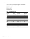
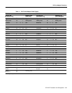
Table 9 lists the 4T port adapter LEDs and their indications.
Table 9 LED Indications
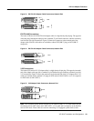
4T Port Adapter Receptacles, Cables, and Pinouts
The following sections describe the serial receptacles on the 4T port adapter, and the cables and
pinouts for the various serial interface cables.
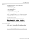
Serial Port Adapter Receptacles and Cables
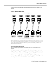
The 4T port adapter and adapter cables allow a high density of interface ports, regardless of the size
of the connectors typically used with each electrical interface type.
All ports use an identical 60-pin, D-shell receptacle that supports all interface types: EIA/TIA-232,
V.35, EIA/TIA-449, X.21, and EIA-530. Each port requires a serial adapter cable, which provides
the interface between the high-density serial port and the standard connectors that are commonly
used for each electrical interface type.
Note The adapter cable determines the electrical interface type and mode of the port (DTE or DCE)
to which it is connected.
LED Label DTE Function DCE Function Color and Function
TD Transmit data out Transmit data in Green
TC Transmit clock in Transmit clock in
(TXCE)
Green
RD Receive data in Receive data out Green
RC Receive clock in Receive clock out Green
LB/CD – – Green: DTR, DSR, RTS, CTS, or DCD active
Yellow: local loop or internal loop active
EN (enable) – – Green: port adapter enabled