


VIP-4R/4T Installation and Configuration 27
Versatile Interface Processor Functions
Following is the procedure for replacing or upgrading DRAM SIMMs.
Step 1 Attach an ESD-preventive wrist strap between you and an unpainted chassis or VIP surface.
Step 2 Disconnect all cables from the VIP and remove it from the chassis using the procedure in
the section “Removing a VIP” on page 16.
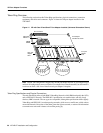
Step 3 Place the VIP on a flat surface (preferably an antistatic mat or foam), and turn it so the face
plate is away from you and the connector edge is toward you. (approximately opposite of
the orientation shown in Figure 11).
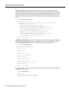
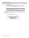
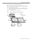
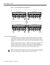
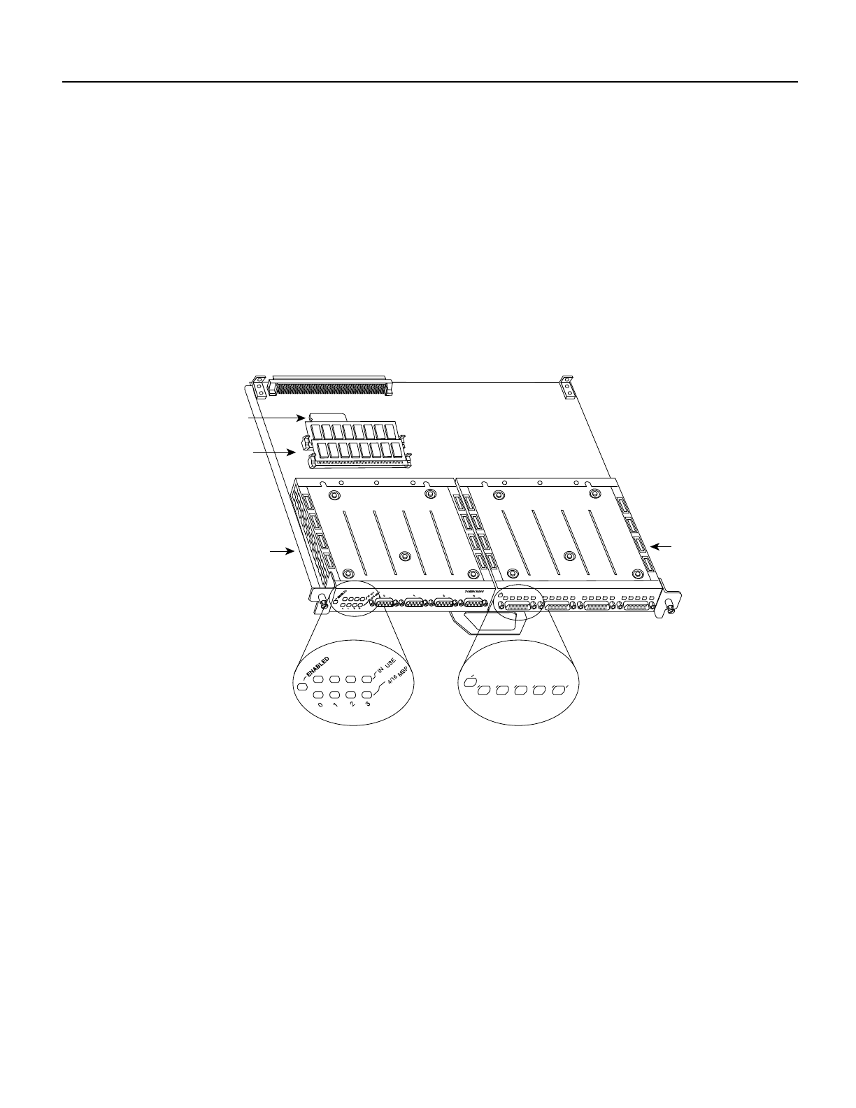
Step 4 Locate the DRAM SIMMs in U1 and U2. (See Figure 11.)
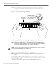
Figure 11 Orientation of DRAM SIMMs (U1 and U2) on VIP Motherboard
H5985
DRAM
SIMMs
Microcode
ROM U1 7
Bus connector
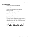
EN
TD
TC
RD
RC
LB
CD
FAST SERIAL
EN
TD
TC
RD
RC
LB
CD
TD
TC
RD
RC
LB
CD
TD
TC
RD
RC
LB
CD
TD
TC
RD
RC
LB
CD
4R in port
adapter
slot 0
4T in port
adapter
slot 1
Port adapter
handles not shown