


28 VIP-4R/4T Installation and Configuration
Versatile Interface Processor Functions
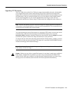
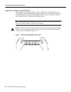
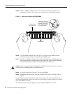
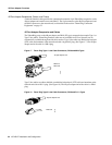
Step 5 Remove a SIMM by pulling outward on the connectors to unlatch it, as shown in the
enlargement in Figure 12. Be careful not to break the holders on the SIMM connector.
Figure 12 Removing and Replacing DRAM SIMMs
Step 6
Using the SIMM orientation shown in Figure 12, position the new SIMM so that the
polarization notch is located at the right end of the SIMM socket.
Step 7 Insert the new SIMM by sliding the end with the metal fingers into the SIMM connector
socket at approximately a 45-degree angle to the system card. Gently rock the SIMM back
into place until the latch on either side snaps into place. (See Figure 12.)
Caution Do not use excessive force, or the connector could break. To prevent damage, do not push
on the center of the SIMMs. Handle each SIMM with care.
Step 8 As required, repeat Steps 5 through 7 for the second SIMM.
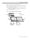
Step 9 Reinstall the VIP in the chassis using the procedure in the section “Installing a VIP” on
page 18.
If error messages relating to memory are displayed once power to the chassis is turned back on, or
the VIP card is installed in a chassis that is already on, repeat Steps 1 through 8, taking care to firmly
reseat each SIMM in its socket.
This completes the procedure for upgrading or replacing DRAM SIMMs on your VIP.
Polarization notch
DRAM SIMM
Pull the tabs away with
your thumbs, bracing your
forefingers against the
posts. Raise the SIMM
to a vertical position.
H2017
Faceplate edge of
the system card