


62 VIP-4R/4T Installation and Configuration
VIP Port Adapter Functions
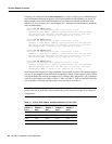
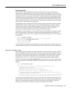
Following is an example of how the show interfaces [type slot/portadapter/port] command displays
status information (including the physical slot and port address) for the interfaces you specify. In
these examples, most of the status information for each interface is omitted, and the four serial
interfaces (0–3) are in chassis slot 3, in port adapter slot 1. (Interfaces are administratively shut down
until you enable them.)
Router# sh int serial 3/1/0
Serial3/1/1 is administratively down, line protocol is down
Hardware is cyBus Serial, address is 0000.0ca5.2300 (bia 0000.0ca5.2389)
MTU 1500 bytes, BW 10000 Kbit, DLY 1000 usec, rely 255/255, load 1/255
Encapsulation ARPA, loopback not set, keepalive set (10 sec)
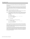
Router# sh int serial 3/1/1
Serial3/1/2 is administratively down, line protocol is down
Hardware is cyBus Serial, address is 0000.0ca5.2300 (bia 0000.0ca5.238a)
MTU 1500 bytes, BW 10000 Kbit, DLY 1000 usec, rely 255/255, load 1/255
Encapsulation ARPA, loopback not set, keepalive set (10 sec)
Router# sh int serial 3/1/2
Serial3/1/3 is administratively down, line protocol is down
Hardware is cyBus Serial, address is 0000.0ca5.2300 (bia 0000.0ca5.238b)
MTU 1500 bytes, BW 10000 Kbit, DLY 1000 usec, rely 255/255, load 1/255
Encapsulation ARPA, loopback not set, keepalive set (10 sec)
Router# sh int serial 3/1/3
Serial3/1/3 is administratively down, line protocol is down
Hardware is cyBus Serial, address is 0000.0ca5.2300 (bia 0000.0ca5.238b)
MTU 1500 bytes, BW 10000 Kbit, DLY 1000 usec, rely 255/255, load 1/255
Encapsulation ARPA, loopback not set, keepalive set (10 sec)
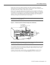
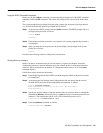
Serial interface port adapters are always numbered as port adapter 1 because VIPs currently support
only one 4T port adapter with the VIP-4R/4T configuration, and the 4T port adapter is always in the
second port adapter slot location (port adapter slot 1). With this VIP configuration, a 4T port adapter
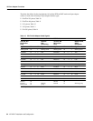
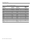
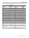
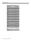
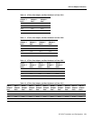
is always in port adapter slot 0. Refer to Table 15, Table 16, Table 17, Table 18, and Table 19 for the
4T port numbers associated with the interface processor slots in your chassis.
Note Table 15, Table 16, Table 17, Table 18, and Table 19 indicate 4T interface port numbers
based on the slots in which they can be installed; they do not represent examples of maximum 4T
configurations.
Table 15 4T Slot, Port Adapter, and Port Numbers in a Cisco 7000
Slot 0/
Adapter 1/
Port n
Slot 1/
Adapter 1/
Port n
Slot 2/
Adapter 1/
Port n
Slot 3/
Adapter 1/
Port n
Slot 4/
Adapter 1/
Port n
0/1/0 1/1/0 2/1/0 3/1/0 4/1/0
0/1/1 1/1/1 2/1/1 3/1/1 4/1/1
0/1/2 1/1/2 2/1/2 3/1/2 4/1/2
0/1/3 1/1/3 2/1/3 3/1/3 4/1/3