


122
Chapter 5 Centronics Parallel Interface
Centronics Parallel Interface
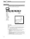
The Centronics interface enables the printer to operate with controllers
designed for buffered Centronics printers. The length of the data cable from
the host computer to the printer must not exceed 15 feet (5 meters).
Centronics Interface Signals
The Centronics interface signals between the host computer and the printer
are defined as follows:
Data Lines 1 through 8. Provide eight standard or inverted levels from the
host that specify character data, plot data, or a control code. Data Line 8
allows access to the extended ASCII character set. You may enable or
disable this line via the Data Bit 8 parameter on the Centronics submenu
(page 107).
Data Strobe. Carries a low true, 100 ns minimum pulse from the host that
clocks data into the printer.
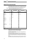
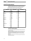
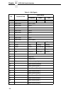
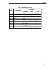
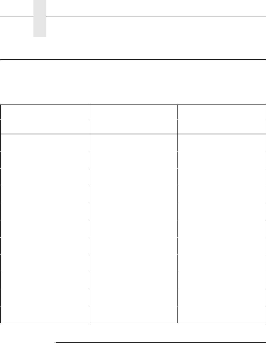
Table 12. Centronics Interface Connector Pin Assignments
Input Signals Output Signals Miscellaneous
Signal Pin Signal Pin Signal Pin
DATA LINE 1
Return
2
20
ACKNOWLEDGE
Return
10
28
CHASSIS GROUND 17
DATA LINE 2
Return
3
21
ONLINE
Return
13
28
GROUND 30
DATA LINE 3
Return
4
22
FAULT
Return
32
29
Spares 14
DATA LINE 4
Return
5
23
PAPER EMPTY
Return
12
28
No Connection 34,35,
36
DATA LINE 5
Return
6
24
BUSY
Return
11
29
+5 Volts 18
DATA LINE 6
Return
7
25
DATA LINE 7
Return
8
26
DATA LINE 8
Return
9
27
DATA STROBE
Return
1
19
PAPER INSTRUCTION
Return
15
29
PRIME
Return
31
30