


130
Chapter 5 RS-232 and RS-422 Serial Interfaces
RS-232 and RS-422 Serial Interfaces
NOTE: The RS-232 and RS-422 serial interface circuit characteristics are
compatible with the Electronic Industry Association Specifications
EIA
®
-232-E and EIA-422-B.
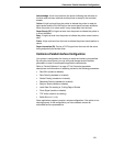
The RS-232 and RS-422 serial interfaces enable the printer to operate with bit
serial devices that are compatible with an RS-232 controller. The input serial
data transfer rate (in baud) is selectable from the printer control panel. Baud
rates of 600, 1200, 2400, 4800, 9600, 19200, 38400, 57600, and 115K are
available. The default is 9600.
NOTE: If you select a baud rate that is 19200 or greater, you may need to
increase the Buffer Size in K parameter from the default (8 Kbyte), to
improve performance.
The input format consists of a single start bit, 7 or 8 data bits, and one or two
stop bits. The number of data bits is determined by printer configuration. The
data bits are interpreted with the least significant bit first. Parity checking is
determined by printer configuration options selected from the control panel.
The printer interface uses a first-in/first-out buffer. The asynchronous
interface accepts data as it is provided by the host. The length of the data
cable from the host computer to the printer must not exceed 50 feet (15
meters) for RS-232 or 4000 feet (1220 meters) for RS-422. A copper
conductor, twisted-pair telephone cable with a shunt capacitance of 16 pF/
foot (52.5 pF/meter) terminated in a 100 ohm resistive load must be used for
the RS-422.
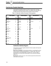
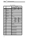
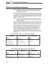
Table 15. RS-232 Serial Interface Connector Pin Assignments
Input Signals Output Signals Miscellaneous
Signal Pin Signal Pin Signal Pin
Receive Data (RD) 3 Transmit Data (TD) 2 Chassis Ground 1
Clear To Send (CTS) 5 Request To Send (RTS) 4 Signal Ground 7
Data Set Ready (DSR) 6 Data Terminal Ready (DTR) 20
Data Carrier Detect (DCD) 8
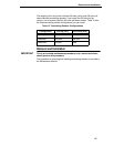
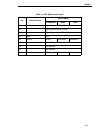
Table 16. RS-422 Serial Interface Connector Pin Assignments
Input Signals Output Signals Miscellaneous
Signal Pin Signal Pin Signal Pin
- Receive Data (-RD) 15 - Transmit Data (-TD) 19 Chassis Ground 1
+ Receive Data (+RD) 17 + Transmit Data (+TD) 25 Signal Ground 7