


Crestron PAC2 Professional Automation Computer
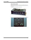
Ports/Connectors
The ports/connectors provided on the top and front panel of the PAC2 are described
in the following paragraphs.
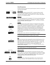
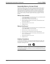
LEFT, RIGHT
LEFT
(24 Y Z G OVERRIDE)
RIGHT
(OVERRIDE G Z Y 24)
These 5-position connectors, rated at 24VDC, 2A maximum load, provide for
Cresnet signals and an additional override contact closure signal. Use the Unit
Interconnect Cable Assembly, supplied with the PAC2, to connect to the lighting
module(s) or a CAEN Block assembly.
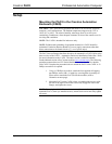
NET A - H
24 Y Z G
24 Y Z G 24 Y Z G
24 Y Z G
These eight segments provide 32 standard (24 Y Z G) Cresnet connectors (in groups
of four) for user interface connections. Each group of four supports 32 electrical
Cresnet connections. Connectors are rated at 24VDC, 2A maximum with internal
power; 3A maximum with external power.
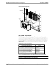
POWER
These connectors are used to supply 24VDC power to the built-in hub segments.
Each connector provides power to a segment pair—POWER 1 provides power to
segments NET A and NET B; POWER 2 provides power to segments NET C and
NET D; etc. Internal power is applied to a segment pair by plugging one of the
supplied 3-pin mini connectors with installed jumper wire into the appropriate
POWER connector. If the power needed for a hub segment exceeds the power
available from the internal supply, remove the jumper from the supplied 3-pin mini
connector and connect the 24VDC and ground wires from an external source to the
EXT and G pins.
POWER
34
G
INT
EXT
G
INT
EXT
1
G
INT
EXT
2
G
INT
EXT
POWER
For more details, refer to “Built-In Cresnet Hub/Repeater” on page 9.
CAUTION: Use only Crestron power supplies for Crestron equipment. Failure to do
so could cause equipment damage or void the Crestron warranty.
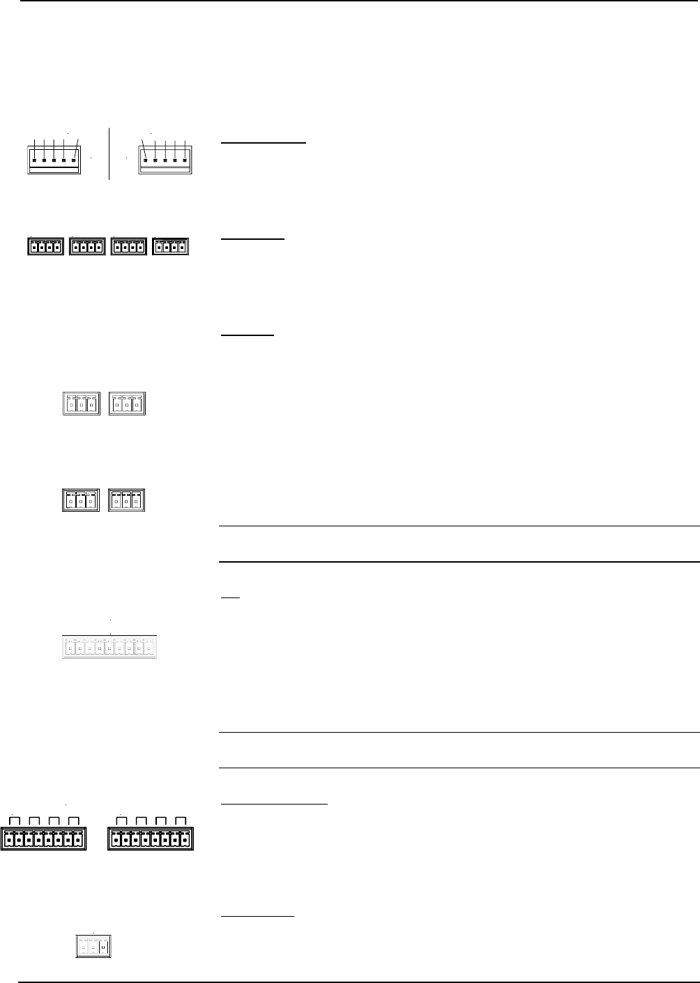
I/O
The I/O port has eight software programmable analog and digital inputs as well as
digital outputs. Digital outputs offer 250mA sink from maximum 24 VDC; catch
diodes for use with "real world" loads. Digital inputs are rated 0 – 24 VDC, 20K
ohms input impedance, logic threshold 1.25 VDC. Analog inputs are rated 0 – 10
VDC, protected to 24 VDC maximum, 20K ohms input impedance; pin-
programmable 2K ohms pullup resistor to +5V. For detailed information, refer to
“Slot 4: C2I-IO8” on page 32.
I/O
1 2 3 4 5 6 7 8 G
NOTE: Digital outputs are TTL values and may not work with devices requiring a
“dry” contact closure (e.g., low voltage motor controllers).
RELAY OUTPUT
RELAY OUTPUT
1 2 3 4
5 6 7 8
Provide eight normally open, isolated relay contact groups. Each relay contact
closure is rated 1A, 30 VAC/DC; MOV arc suppression is provided across contacts
for use with "real world" loads. For detailed information, refer to “Slot 5: C2I-RY8”
on page 34. Refer to “Bussing Strip Installation” on page 16 for information on
commoning (linking) of the terminal block connections.
OVERRIDE
OVER
RIDE
G L R
Provides external dry contact closure inputs directly to the 5-position Cresnet
interconnect connectors, LEFT and RIGHT. When a switch contact closure is
Operations Guide – Doc. 5941 Professional Automation Computer: PAC2 • 7