


Crestron PAC2 Professional Automation Computer
NOTE: The LAN LEDs are active only if the optional single port or dual port
Ethernet card (which is field installed) occupies the Z-BUS slot. LAN A is used for a
single port Ethernet card; LAN A and B are used for the dual port card.
LNK A, LNK B (LAN)
These LEDs illuminate when the Ethernet card has established a valid Ethernet
connection.
ACT A, ACT B (LAN)
These LEDs illuminate when there is communication (activity) at the respective port
on the Ethernet card.
Reset Buttons
Two buttons are provided on the top panel of the 2-Series integrated control systems.
Refer to the description of each below.
HW-R
Pressing this button initiates system hardware reset. (Same effect as disconnecting
and reconnecting power-reinitializes operating system and program.)
SW-R
Pressing this button alone momentarily while the system is running restarts the
program. Pressing this button in combination with the HW-R button performs a
system restart without reinitializing the program (refer to “Troubleshooting
Communications” on page 21).
Built-In Cresnet Hub/Repeater
The built-in Cresnet Hub/Repeater serves as a repeater, splitter, and wiring block.
The hub allows for 256 or more devices; 32 per segment (A-H) and distribution up to
3000 feet per segment.
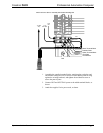
There are eight independent segments, each with four Cresnet connectors wired in
parallel. Each segment has a dedicated driver/receiver for Cresnet communication. In
addition, there is a master NET port on the front panel. The eight NET (A-H)
activity LEDs illuminate when a device on the respective segment transmits data.
Segments that are not in use or have devices that are not polled by a SIMPL program
are logically ‘disconnected’ from the other segments in operation. The LEDs for
these segments are not illuminated.
CAUTION: Use only Crestron power supplies for Crestron equipment. Failure to do
so could cause equipment damage or void the Crestron warranty.
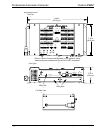
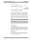
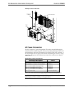
Power for the hub is supplied through POWER ports 1, 2, 3, and 4, to segment pairs,
as shown in the illustration on the next page. When power is applied, the LED
adjacent to the port is illuminated.
Operations Guide – Doc. 5941 Professional Automation Computer: PAC2 • 9