


Professional Automation Computer Crestron PAC2
Bussing Strip Installation
The PAC2 is supplied with two brass bussing strips to facilitate commoning (linking)
of the S5 Relay Output terminal block connections. The bussing strips are
constructed with four terminal block positions, and may be trimmed to size for
various applications or different devices. One strip is supplied for each
8-position terminal block.
1. To utilize the bussing strip, determine the number of relays to be
commoned for the equipment being installed. If less than four, the strip
can be trimmed to size with a pair of scissors or wire snips.
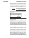
2. Loosen the terminal block screws and insert the first leg of the bussing
strip into the first common position on the terminal block. The strip
engages the other common positions automatically.
3. Remove approximately 1/8" of the jacket from the common wire and
insert the conductor into one of the terminal block common positions.
Tighten the terminal block screws to lock the wire and bussing strip
into place. Insulate the strip by folding a piece of ¾" wide vinyl
electrical tape over the spine and as much of the individual legs as
possible. Excess tape at each end of the strip should be pressed closed,
then trimmed to within approximately 1/16" of the end of the strip.
4. When wiring the remaining conductors, remove approximately 1/8" of
the jacket and insert the wires into the proper terminal block positions.
To prevent the possibility of electrical shorts, it is essential that these
conductors do not touch any uninsulated portion of the bussing strip.
5. Secure the wires connected to the terminal block with a tie wrap around
the bussing strip to provide strain relief.
Network Wiring
CAUTION: Use only Crestron power supplies for Crestron equipment. Failure to do
so could cause equipment damage or void the Crestron warranty.
CAUTION: Possible equipment damage if miswired.
CAUTION: Exceeding the power output (maximum 50W) of the 2-Series
automation control system can result in erratic system behavior, system shutdown or
a blown fuse.
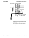
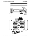
NOTE: When installing network wiring, refer to the latest revision of the wiring
diagram(s) appropriate for your specific system configuration, available from the
Downloads | Product Manuals | Software and Wiring Diagrams section of the
Crestron website (www.crestron.com)
.
NOTE: Do not power up system until all wiring is verified. Care should be taken to
ensure data (Y, Z) and power (24, G) connections are not crossed.
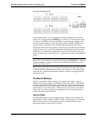
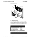
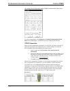
NOTE: The PAC2 automation control system has thirty-three 4-pin network
connectors. Use the following Crestron products to interconnect to other devices
within a network (some permit network testing):
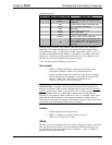
- CNTBLOCK, Network Terminal Block
- CNHBLOCK, Multi-Type Network Distribution Block
- CNXHUB, Cresnet Hub/Repeater (regenerates Cresnet signals, so Network
Analyzer results are not accurate)
- ST-CNB, SmarTouch/Cresnet Terminal Expander
16 • Professional Automation Computer: PAC2 Operations Guide – Doc. 5941