


Professional Automation Computer Crestron PAC2
received between the “G” connection and the “L” or “R” connection (R is used in a
double-wide enclosure only), the respective left or right column of modules will set
the lights to the programmed emergency override state. The connector is rated at 5V,
10mA maximum.
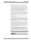
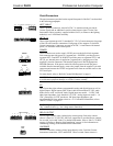
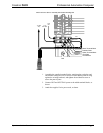
BACKUP NET INPUT
BACKUP
NET INPUT
24 Y Z G
FAULT
F G
This connector (Crestron network port labeled 24 Y Z G) allows a backup control
system connected here via Cresnet cable to automatically take control of the Cresnet
network upon a failure of the internal processor. The connector is rated at 24VDC,
Class 2 power source. A 24VDC power supply is diode “ORed” with the internal
supply and will power the system if the built-in supply fails. Cresnet will switch over
upon a built-in watchdog detecting failure of the CPU. The FAULT LED indicates
the failure.
FAULT
Provides a dry contact closure fault signal to notify an external control system when
the PAC2 has a system fault. This output should be connected to a digital input of the
backup computer. The fault signal is active low. A fault is defined as the CPU not
interacting with Cresnet for 10 seconds. The watchdog will switch back if the backup
computer’s Cresnet is inactive for 10 seconds.
COMPUTER
COMPUTER
This DB9F connector is used when programming with a PC. The port is modem
compatible. The modem and/or PC program cable (standard male to female straight-
through) is not supplied.
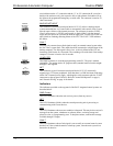
NET
NET
24 Y Z G
24VDC 50W
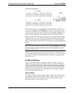
This connector (typical Crestron network port labeled 24 Y Z G) electrically
supports up to 32 Cresnet peripherals. Note that there is a 50W maximum load rating
on the PAC2 internal power supply, which applies to this connector plus the 32 NET
connectors on the top panel. Refer to “Built-In Cresnet Hub/Repeater” on page 9,
and “Network Wiring” on page 16 for details.
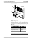
Indicators
The indicators provided on the top panel of the PAC2 integrated control systems are
described below.
PWR (Power)
This LED illuminates when the unit receives power (from any source).
NET
This LED illuminates (blinks) when the central processing unit is processing or
communicating with Cresnet devices.
ERR
This LED illuminates when an error condition is detected. This may be the result of a
message from the system, a hardware or software failure, a missing/wrong card
placed in a slot, or a programming error. To decipher content, examine the message
available through Viewport.
FAULT
This LED illuminates when a fault signal is sent to notify an external control system
that the PAC2 has switched control to a backup system, since the main system was
detected to be inactive.
8 • Professional Automation Computer: PAC2 Operations Guide – Doc. 5941