


Professional Automation Computer Crestron PAC2
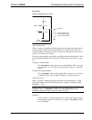
Analog Input Mode
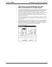
In analog input mode, the Versiport is typically tied to a resistive load (such as a
humidity sensor) or a voltage source (both can be represented by box "A" in the
Versiport diagram).
When a resistive load is tied to a Versiport, the corresponding pullup resistor must be
enabled (again, this means that <pu-disable> should be given the signal name 0 or
left undefined). This creates a voltage divider and provides a varying voltage level,
based on the current resistance of the sensor for the C2I-IO8 to read.
Example 4:
A resistive humidity sensor is tied to Versiport 1 (and <pu-disable1> is low
or undefined). <i1> will assume the corresponding analog value.
When a voltage source is tied to a Versiport, the corresponding pullup resistor should
be disabled (the only case where the default setting should be overridden). This
allows the C2I-IO8 to read the value of the voltage source directly.
Example 5:
A voltage source is tied to Versiport 1 and <pu-disable1> is given the
signal name 1. <i1> will assume the corresponding analog value (ranging
from 0 to 65535, or 0 to +10V on the input pin).
The C2I-IO8 does not propagate all changes in the analog values of its Versiports,
since this can lead to undesirable results if the input source is not clean or has jitter.
Rather, the <MinChange> signals should be used to specify a "minimum change"
value, such that the C2I-IO8 will not propagate the new value until it changes by
<MinChange>. (The default minimum change value is 2048.)
Example 6:
A voltage source is placed on Versiport 1 and <MinChange1> is set to 10
via an Analog Initialize symbol. The value of <i1> will not be propagated
until it changes by at least 10. If the current value is 500, then a new value
will not be reported until it changes to 510 or 490.
Slot 5: C2I-RY8
The C2I-RY8 provides eight isolated relays for controlling low voltage contact
closure devices such as drapes, screens and lifts.
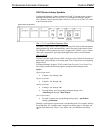
In Program Manager, drag the C2I-RY8 symbol from Program View to Detail View.
The symbol contains the following signals:
Signals
• 8 relays: <A1> through <A8>
When a signal goes high, the corresponding relay closes for as long as the signal
remains high. When the signal goes low, the relay opens. If a signal is undefined, the
relay is open.
Slot 6: C2Net-Device
The C2Net-Device slot enables the PAC2 to control up to 252 Cresnet devices. Each
Cresnet device is assigned a unique identifier called a Net ID, which is a
hexadecimal value ranging from 03 to FE.
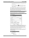
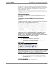
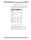
To view the list of supported devices, expand the control system in the bottom pane
of System Views and double-click the C2Net-Device slot, or right-click and select
Add Item from the submenu. Supported devices include network control modules,
lighting modules and a variety of Crestron wired touchpanels.
34 • Professional Automation Computer: PAC2 Operations Guide – Doc. 5941