


Crestron PAC2 Professional Automation Computer
When calculating the wire gauge for a particular network run, the length of the run
and the power factor of each network unit to be connected must be taken into
consideration. If network units are to be daisy-chained on the run, the power factor
of each network unit to be daisy-chained must be added together to determine the
power factor of the entire chain. The length of the run in feet and the power factor of
the run should be used in the following resistance equation to calculate the value on
the right side of the equation.
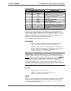
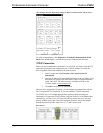
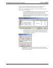
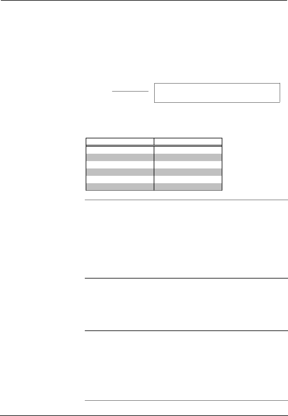
Resistance Equation
R = Resistance (refer to table below).
L = Length of run (or chain) in feet.
PF = Power factor of entire run (or chain).
R <
L x PF
40,000
Where:
The required wire gauge should be chosen such that the resistance value is less than
the value calculated in the resistance equation. Refer to the table after this paragraph.
Wire Gauge Values
RESISTANCE (R) WIRE GAUGE
4
16
6
18
10
20
15
22
13
Doubled CAT5
8.7
Tripled CAT5
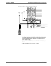
NOTE: All network wiring must consist of two twisted-pairs. One twisted pair is
the +24V conductor and the GND conductor and the other twisted pair is the Y
conductor and the Z conductor.
NOTE: When daisy chaining network units, always twist the ends of the incoming
wire and outgoing wire that share a pin on the network connector. After twisting the
ends, tin the twisted connection with solder. Apply solder only to the ends of the
twisted wires. Avoid tinning too far up or the tinned end becomes brittle and breaks.
After tinning the twisted ends, insert the tinned connection into the network
connector and tighten the retaining screw. Repeat the procedure for the other three
network conductors.
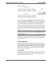
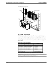
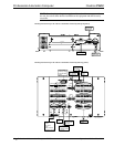
Hardware Hookup
Refer to the hookup diagrams on the next page, and aside from attaching power last,
complete the connections in any order. Refer to “Network Wiring” on page 16 and
“Built-In Cresnet Hub/Repeater” on page 9 when making network connections.
NOTE: To prevent overheating, do not operate this unit in an area that exceeds the
environmental temperature range listed in the table of specifications. Consideration
must be given if installed in a closed or multi-unit rack assembly since the operating
ambient temperature of the rack environment may be greater than the room ambient.
Contact with thermal insulating materials should be avoided on all sides of the unit.
NOTE: The maximum continuous current from equipment under any external load
conditions shall not exceed a current limit that is suitable for the minimum wire
gauge used in interconnecting cables. The ratings on the connecting unit's supply
input should be considered to prevent overloading the wiring.
Operations Guide – Doc. 5941 Professional Automation Computer: PAC2 • 17