


196 Small Form Factor Computer
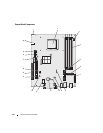
PCI 2.3
124-pin connector
PCIe-X16
164-pin connector
Internal USB
10-pin connector
Intrusion switch
3-pin connector
Speaker
5-pin connector
Memory modules
four 240-pin connectors
Power 12V
4-pin connector
Power
24-pin connector
Battery
2-pin socket
Front panel
40-pin connector
Key Combinations
<Ctrl><Alt><Del> in Microsoft
®
Windows
®
XP and Windows Vista, brings up the
Windows Security window; in MS-DOS
®
mode, restarts (reboots)
the computer
<F2> or <Ctrl><Alt><Enter> starts embedded system setup (during system start-up only)
<F12> or <Ctrl><Alt><F8> displays a boot device menu that allows the user to enter a device
for a single boot (during system start-up only) as well as options to
run hard-drive and system diagnostics
Controls and Lights
Power control front of chassis - push button
Power light (within the power
button)
green light — Blinking green indicates a sleep mode; solid green
indicates a power-on state.
amber light — Blinking amber indicates a problem with an
installed device; solid amber indicates an internal power problem
(see "Power Problems" on page 321).
Hard-drive access light front panel - green
Link light front panel - solid green light indicates network connection
Link integrity light (on integrated
network adapter)
rear panel - green light for 10-Mb operation; orange light for 100-
Mb operation; yellow light for a 1000-Mb (1-Gb) operation
Activity light (on integrated network
adapter)
rear panel - yellow blinking light
Diagnostic lights front panel - four lights. See "Diagnostic Lights" on page 330.
Standby power light AUX_PWR on the system board
Connectors