• DIMM configuration (number of ranks)
• Maximum frequency of the DIMMs
• Number of DIMMs populated per channel
• DIMM operating voltage
• System profile selected (Performance Optimized)
• Maximum supported DIMM frequency of the processors
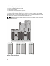
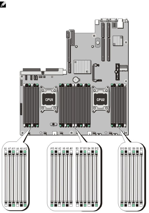
The system contains 24 memory sockets split into two sets of 12 sockets, one set for each processor.
Each 12-socket set is organized into four channels. In each channel, the release levers of the first socket
are marked white, the second socket black, and the third socket green.
NOTE: DIMMs in sockets A1 to A12 are assigned to processor 1 and DIMMs in sockets B1 to B12 are
assigned to processor 2.
Figure 12. Memory socket locations
40


