42 Preparing Your Systems for Clustering
www.dell.com | support.dell.com
The split-bus module has only one LED indicator (see Figure 3-1 for location), which is
illuminated when the module is receiving power.
Enclosure Management Module (EMM)
The EMM serves two primary functions in your storage system:
• SCSI bus expansion — Acts as a buffer for the SCSI bus, electrically dividing the bus into two
independent segments while logically allowing all SCSI bus traffic to pass through it
transparently. The buffer improves the quality of the SCSI signals and allows longer cable
length connections.
• Management functions — Includes SCSI enclosure services (SES) and SCSI accessed
fault-tolerant enclosures (SAF-TE) reporting to the host initiator, control of all enclosure
LED indicators, and monitoring of all enclosure environmental elements such as temperature
sensors, cooling modules, and power supplies.
A system with redundant enclosure management features two EMMs that are designated as
primary and secondary and can be configured in either a cluster, joined-bus, or split-bus mode.
A nonredundant configuration consists of one EMM and one SCSI terminator card, and can be
configured in a joined-bus mode only. In a redundant system, only one EMM per SCSI bus is
active at one time, so only one EMM per SCSI bus can respond to SCSI commands from
an initiator.
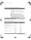
Table 3-3. Split-bus Module Modes and Functions
Mode Position of Bus
Configuration
Switch
Function
Joined-bus mode Up Low Voltage Differential (LVD) termination on the
split-bus module is disabled, electrically joining the
two SCSI buses to form one contiguous bus. In this
mode, neither the split-bus nor the cluster Light-
Emitting Diode (LED) indicators on the front of the
enclosure are illuminated.
Split-bus mode Center LVD termination on the split-bus module is enabled
and the two buses are electrically isolated, resulting in
two seven-drive SCSI buses. The split-bus LED
indicator on the front of the enclosure is illuminated
while the system is in split-bus mode.
Cluster mode Down LVD termination is disabled and the buses are
electrically joined. The cluster LED on the front of the
enclosure is illuminated while the system is in
cluster mode.
se500wbk1.book Page 42 Thursday, June 16, 2005 4:19 PM


