


4 Configuration and Operation
28
4.7.1 Switching Model
The basic switching model assumes that at system initialization all incoming
T1/E1 timeslots and all resource board output timeslots are connected up to
channels on the CT bus and that these connections are never changed. This
has the advantage that once the on-board CT bus drivers have been set up
they are never changed so the chances of inadvertently causing CT bus
conflict is minimized. It also means that the user can predict the exact CT bus
channels where any input timeslot can be located and this in turn can assist
with fault diagnosis and general system test.
It is also possible to generate fixed patterns on any T1/E1 output timeslots to
provide the correct idle pattern for presentation to the network on all circuits
where there is no active call.
Having completed the system initialization, all drives to the CT bus are set
up. Then, on a dynamic (call by call) basis, the connectivity must be modified
when a new call arrives and when it finishes.
When a new call arrives, the application, in general, needs to initiate two
listen commands. One command causes the resource to listen to the
appropriate CT bus channel to hear the incoming voice path and the other
causes the T1/E1 interface to listen to the output from the resource board to
generate the outgoing voice path.
When a call clears, the application needs to initiate generation of the fixed
idle pattern towards the network operation (and may wish to connect an idle
pattern to the resource board).
4.7.2 Static Initialization
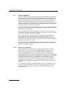
Static initialization is handled by the s7_mgt utility. For each T1/E1 line
interface unit, user must include an LIU_SC_DRIVE command in the
config.txt file. The syntax for this command is detailed in appendix A.
The LIU_SC_DRIVE command has several parameters. board_id and
liu_id together uniquely identify the affected line interface unit. sc_channel
is the channel number of the first channel on the CT bus that is to be used for
timeslots from the specified LIU. ts_mask is a mask identifying which
timeslots on the T1/E1 interface are carrying voice circuits (as opposed to
signaling) and therefore need to be connected to the CT bus. The least
significant bit of ts_mask must always be zero when driving from an T1/E1
interface.
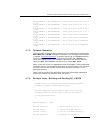
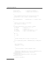
As an example, consider a two board system where the first board has 4 E1
ports and the second board has 4 T1 ports. We allow the first 512 CT bus
channels to be used by other boards in the system and therefore start at
sc_channel 512.