6 Message Reference
48
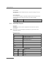
Bit 15 is set to 1 to disable the link, or zero to enable the link.
All other bits are reserved for future use and must be set to zero.
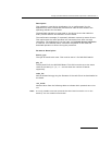
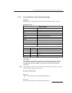
linkn_slc - Signaling link code
The signaling link code for the link, which must be in the range 0 to 15. The
signaling link code must be agreed with the administration at the other end of
the link and must be unique within a link set. Usually, the first link in a link
set is assigned the value 0, the next 1, and so on.
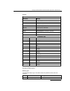
linkn_adj_pc - Adjacent point code
The point code of the signaling point at the remote end of the link. Must be in
the range 0 to 16383 for 14 bit point code operation or 0 to 16777215 for 24
bit point code operation.
Note: All links in a link set must have the same adjacent point code.
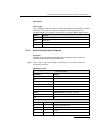
linkn_stream - Signaling stream
When linkn_timeslot is set to a non-zero value, the linkn_stream is the logical
identity of the T1/E1 line interface (liu_id - in the range 0 to one less than the
number of LIUs fitted) containing the signaling link.
Note: For the SPCI2S, stream identifiers for the PCM interfaces are implemented on
streams 2 and 3.
linkn_timeslot - Signaling timeslot
The timeslot used for signaling. For an E1 interface, the valid range is
1 ... 31. For a T1 interface, the valid range is 1 ... 24. Alternatively, the
timeslot may be set to zero, and the switch path set up manually using the
switch control messages.
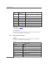
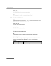
Status Response
The confirmation message (if requested) indicates success by status of zero.
On error, the following status value can be found in the confirmation
message.
Value Description
0xff The Board Configuration Request has failed.


