


Dialogic
®
DSI SPCI Network Interface Boards Programmer's Manual Issue 5
45
If the board is not licensed to run the requested software configuration,
status value of 0xfe is returned.
Parameter Description:
flags - Global flags
Bit 0 is set to 1 to indicate that the user does not wish to use signaling
software. This allows operation of the board without a software license button
providing the board is used only for T1/E1 interface and switching purposes.
If signaling software is required, then this bit must be set to zero.
Bit 9 is set to 1 to disable automatic MTP route configuration, in which case
the user must send individual MTP Route Configuration messages for each
destination. When set to zero, the board automatically configures an MTP
route to each adjacent signaling point using the link set directly connected to
the signaling point.
Bit 10 is reserved for future use and must be set to 1.
Bit 12 is set to 1 to cause all signaling links to be automatically activated.
Usually, this bit is set to zero and the user sends individual MTP Link
Activation requests to activate each link.
Bit 15 is set to 1 for diagnostic purposes to cause the results of internal
board configuration to be passed to the host. When set, all confirmation
messages generated internally on the board during the configuration
sequence are sent to the module_id 0xdf on the host.
All other bits are reserved for future use and must be set to zero.
l1_flags - level 1 flags
Bit 0 controls the reference source used for on-board clocks when acting as
CT bus Primary Master. If set to 1, the clock is recovered from one of the line
interfaces. If set to zero, the on-board clock oscillator is used.
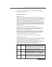
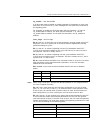
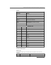
Bit 6 and 7 together select the initial CT bus clocking mode as shown in the
following table. The clocking mode can be modified subsequently and
dynamically using the MVD_MSG_CNFCLOCK message.
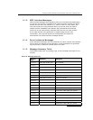
Bit 7 Bit 6 CT bus clocking mode
0 0
The CT bus interface is disabled - The board is electrically
isolated from the other boards using the CT bus. The CT bus
connection commands may still be used, but the connections made
are only visible to this board. The on-board clocks are synchronized
to the source selected by bit 0 of this flags parameter.
0 1
Primary Master, A Channel - The board drives CT bus clock set A
using the clock source selected by bit 0 of this flags parameter.
1 0
Secondary Master, B Channel - The board is configured to drive
clock set B in Secondary Master mode. The on-board clocks are
synchronized to the CT bus clock set A. It will automatically switch
to become Primary Master if the board driving clock set A fails.
1 1
Slave, initially A Channel – The board uses the CT bus clocks,
which must be generated by another board on the CT bus. Initially
the board recovers from clock set A, though will switch over
automatically to recover from clock set B if set A fails.