


Dialogic
®
DSI SPCI Network Interface Boards Programmer's Manual Issue 5
47
up_enable - User Part Enable
A 16 bit mask used to enable or disable reception of messages on a per user
part basis. If bit N is set to 1, then messages for user part N are received by
the signaling point.
For example, to enable the TUP User Part (Service indicator = 4) set the
up_enable field to 0x0010, For ISUP (Service Indicator = 5), set the
up_enable field to 0x0020. To use both TUP and ISUP, set up_enable to
0x0030.
linkn_flags - Per link flags
Bit 0 is set to 1 to force the use of the emergency proving period during link
alignment. This bit is usually set to zero and uses the appropriate proving
period according to Q.703.
Bit 1 is set to 1 to cause a signaling link test (in accordance with ITU-T
Q.707) to be carried out before a link is put into service, or zero if a test is
not required. This bit is usually set to 1.
Bit 2 is set to 1 to cause a signaling link test (in accordance with ITU-T
Q.707) to be carried out every 30 seconds. This bit is usually set to 1, but is
ignored if Bit 1 is set to zero.
Bit 8 is used to select the MTP2 error correction mode. It is set to 1 to select
PCR (Preventive Cyclic Retransmission) operation, or zero for the Basic
Method of Error Correction.
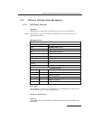
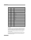
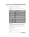
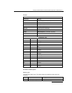
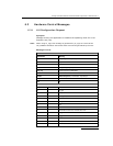
Bits 10 and 11 are used to select the data rate for the link as detailed
below.
Bit 11 Bit 10 Data Rate
0 0 64kbps
1 1 56kbps
0 1 48kbps
Note: When using a serial port, 56 kbps and 48 kbps operation is only supported when
the clock is applied externally.
Bit 13 is only used when the link has been configured to run over a serial
port (i.e., bit 14 is set). If set to 1, an external clock is used (Receive clock).
If set to zero, an internal clock (Transmit clock) is used. If the link has not
been configured to run over a serial port, this bit must be set to zero.
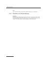
Bit 14 is set to 1 to use a serial port, rather than a PCM timeslot for this link.
In this mode the stream and timeslot parameters for this link are ignored
(and must be set to zero). If this bit is set to zero, the link uses the specified
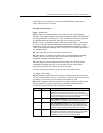
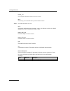
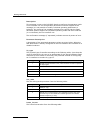
stream and timeslot. The serial port used by the signaling processors for each
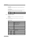
link is fixed, according to the following table:
linkn Serial Port
0 B
1 A
2 Cannot be used for a serial port.
3 Cannot be used for a serial port.