


6 Message Reference
64
Timeslots containing SS7 signaling processed by the signaling processor on
the DSI SPCI Board should not be included in the timeslot mask. Usually, the
mask should be set to include all bearer (voice) timeslots but no signaling
timeslots. Bit 0 (corresponding to timeslot 0 on the LIU) must not be set as
timeslot 0 for an E1 interface contains synchronization information whilst
timeslot 0 for a T1 interface does not exist.
As an example, for an E1 interface with SS7 signaling on timeslot 16, and the
remaining 30 timeslots used for voice circuits, ts_mask should be set to value
0xfffefffe. For a T1 interface with signaling on timeslot 24, ts_mask must be
set to value 0x00fffffe.
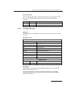
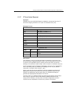
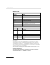
mode
This parameter controls how the CT bus channels are allocated. Usually,
(mode=1) the first timeslot connected to the CT bus is connected to
sc_channel and each subsequent timeslot that is selected is connected to
the next CT bus channel. This allows maximum utilization of channels on the
CT bus.
An alternative mode (mode=2) (only used if there is a specific requirement
for it) associates (but does not necessarily connect) timeslot 0 on the LIU
with sc_channel and subsequent timeslots on the LIU with subsequent CT
bus channels. Connections are only made when the corresponding bit in the
timeslot mask is set to 1. This mode of operation preserves the spacing
between timeslots that was originally found on the T1/E1 interface but does
result in a number of CT bus channels being not used.
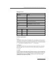
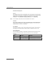
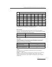
Status Response
The confirmation message (if requested) indicates success by status of zero.
On error, the following status value can be found in the confirmation
message.
Value Mnemonic Description
0xff None Setup failed