16-
H
ARDWARE SETUP
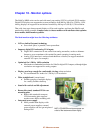
Chapter 3 - Hardware setup
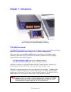
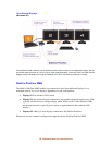
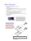
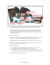
1. Unpack all SideCar components. You should have:
SideCar chassis
Power supply transformer and AC power cord
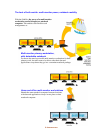
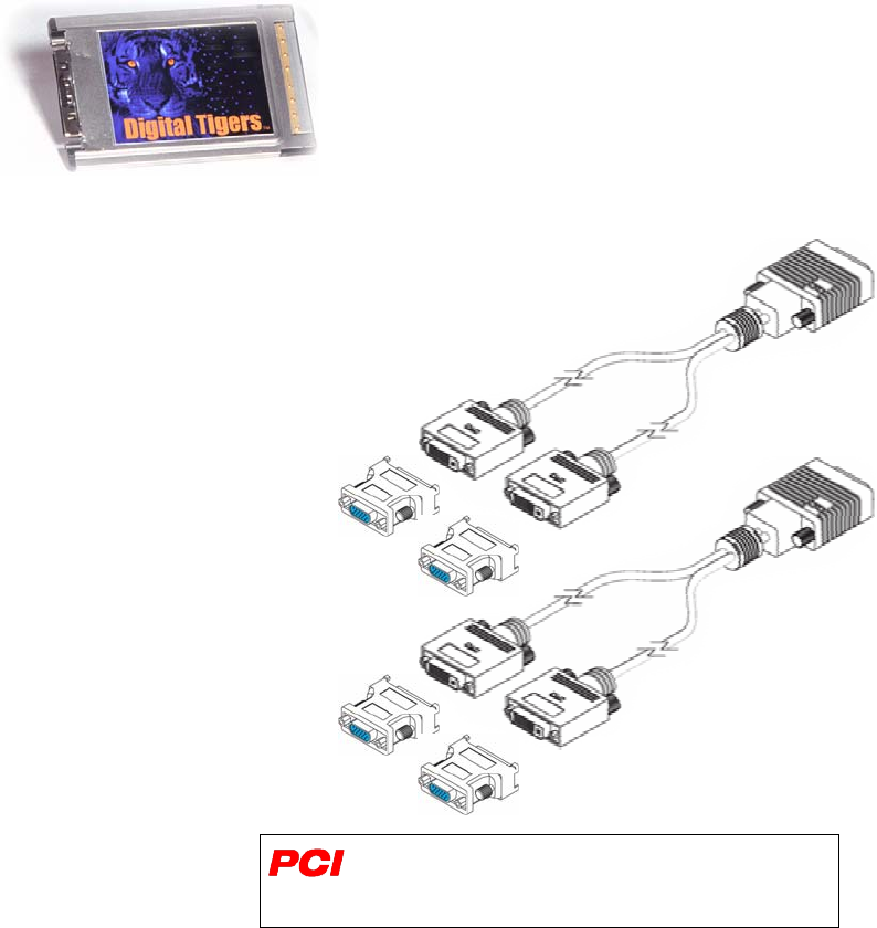
PC Card* notebook interface card; also known as PCMCIA card or CardBus interface
(shown below left)
1-meter SideCar / computer interface cable – connects SideCar to PC Card (or to PCI
adapter)
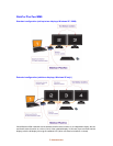
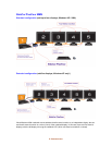
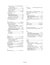
Y-cable dual-DVI display breakout cable(s) (shown below right)
o One breakout cable is supplied with the SideCar PlusTwo MMS.
Two are supplied with the SideCar PlusFour MMS.
DVI-to-VGA (HD15) display output adapters, one per DVI output connector (shown
below right next to Y-cables)
Installation CD
This user manual
*Some SideCar versions have a PCI adapter interface
as a substitute for the PC Card; the PCI adapter is
installed in a notebook docking station or desktop PC.
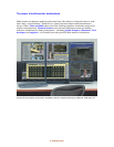
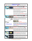
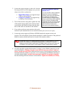
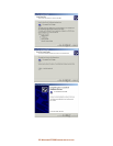
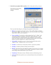
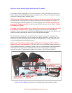
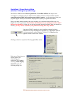
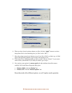
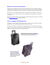
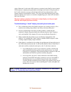
Display output Y-cables with dual DVI
connectors, shown with optional VGA
(HD15) adapters (supplied). Each Y-cable
supports two displays. Large Y-cable
connector (right side) attaches to the
matching LFH connector on rear of the
SideCar. Be extremely careful not to
bend the closely spaced pins on the
SideCar LFH connectors. (Bending these
pins can temporarily disable one or more
displays.) Once the cable is attached to the
SideCar, tighten thumbscrews firmly.
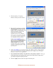
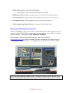
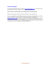
PC Card notebook interface card* (left); also
known as PCMCIA card or CardBus interface.
Attach 1-meter interface cable to connector at left,
securely tighten cable thumbscrews, and insert
card firmly into notebook PC Card slot. (Use
bottom slot if two slots are available.) Connect
other end of interface cable to matching connector
at rear of the SideCar, and tighten firmly.