


xStack
®
DES-3200-10/18/28/28F Layer 2 Ethernet Managed Switch User Manual
VLANs
Understanding IEEE 802.1p Priority
Priority tagging is a function defined by the IEEE 802.1p standard designed to provide a means of managing traffic on
a network where many different types of data may be transmitted simultaneously. It is intended to alleviate problems
associated with the delivery of time critical data over congested networks. The quality of applications that are
dependent on such time critical data, such as video conferencing, can be severely and adversely affected by even
very small delays in transmission.
Network devices that are in compliance with the IEEE 802.1p standard have the ability to recognize the priority level of
data packets. These devices can also assign a priority label or tag to packets. Compliant devices can also strip priority
tags from packets. This priority tag determines the packet's degree of expeditiousness and determines the queue to
which it will be assigned.
Priority tags are given values from 0 to 7 with 0 being assigned to the lowest priority data and 7 assigned to the
highest. The highest priority tag 7 is generally only used for data associated with video or audio applications, which
are sensitive to even slight delays, or for data from specified end users whose data transmissions warrant special
consideration.
The Switch allows you to further tailor how priority tagged data packets are handled on your network. Using queues to
manage priority tagged data allows you to specify its relative priority to suit the needs of your network. There may be
circumstances where it would be advantageous to group two or more differently tagged packets into the same queue.
Generally, however, it is recommended that the highest priority queue, Queue 7, be reserved for data packets with a
priority value of 7. Packets that have not been given any priority value are placed in Queue 0 and thus given the
lowest priority for delivery.
Strict mode and weighted round robin system are employed on the Switch to determine the rate at which the queues
are emptied of packets. The ratio used for clearing the queues is 4:1. This means that the highest priority queue,
Queue 7, will clear 4 packets for every 1 packet cleared from Queue 0.
Remember, the priority queue settings on the Switch are for all ports, and all devices connected to the Switch will be
affected. This priority queuing system will be especially beneficial if your network employs switches with the capability
of assigning priority tags.
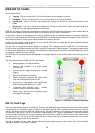
VLAN Description
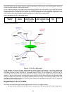
A Virtual Local Area Network (VLAN) is a network topology configured according to a logical scheme rather than the
physical layout. VLANs can be used to combine any collection of LAN segments into an autonomous user group that
appears as a single LAN. VLANs also logically segment the network into different broadcast domains so that packets
are forwarded only between ports within the VLAN. Typically, a VLAN corresponds to a particular subnet, although not
necessarily.
VLANs can enhance performance by conserving bandwidth, and improve security by limiting traffic to specific domains.
A VLAN is a collection of end nodes grouped by logic instead of physical location. End nodes that frequently
communicate with each other are assigned to the same VLAN, regardless of where they are physically on the network.
Logically, a VLAN can be equated to a broadcast domain, because broadcast packets are forwarded to only members
of the VLAN on which the broadcast was initiated.
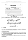
Notes About VLANs
No matter what basis is used to uniquely identify end nodes and assign these nodes VLAN membership, packets
cannot cross VLANs without a network device performing a routing function between the VLANs.
The Switch supports IEEE 802.1Q VLANs and Port-Based VLANs. The port untagging function can be used to
remove the 802.1Q tag from packet headers to maintain compatibility with devices that are tag-unaware.
The Switch's default is to assign all ports to a single 802.1Q VLAN named "default."
The "default" VLAN has a VID = 1.
The member ports of Port-based VLANs may overlap, if desired.
58