


DES-3326S Layer 3 Fast Ethernet Switch User’s Guide
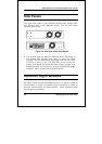
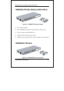
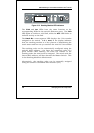
38 Identifying External Components
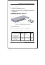
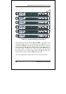
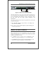
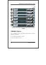
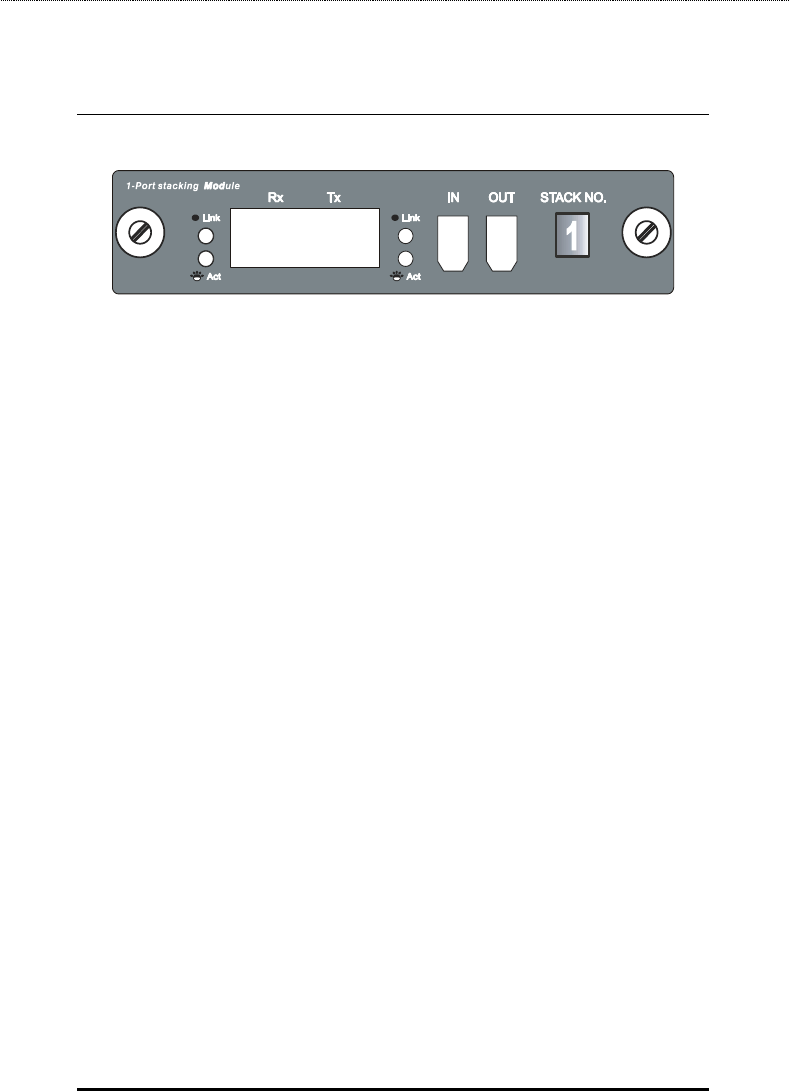
Figure 3-13. Stacking Module LED Indicators
The Link and Act LEDs have the same function as the
corresponding LEDs for the switch’s Ethernet ports. The Link
LED lights to confirm a valid link, while the ACT LED blinks to
indicate activity on the link.
The Stack No. seven-segment LED displays the Unit number
assigned to the switch. A 0 (a zero) in the display indicates
that the stacking module is in the process of determining the
stack status and has not yet resolved the switch’s Unit number.
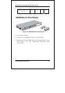
The stacking order can be automatically configured using the
switch’s MAC address − the lower the numerical value of a
given switch’s MAC address, the lower the number in the
stacking order the switch will be assigned. The switch with the
lowest MAC address, will then become the Master Switch. This
is the Stacking Module’s default mode.
Alternatively, the stacking order can be manually assigned
using the console’s Command Line Interface (CLI).