


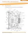
Controls, LEDs, and Connectors
MVME2500 Installation and Use (6806800L01H)
39
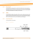
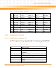
3.3.2 Onboard LEDs
The onboard LEDs are listed below. To view its location on the board, see Figure 3-1 on page 35.
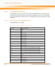
3.4 Connectors
This section describes the pin assignments and signals for the connectors on the MVME2500.
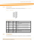
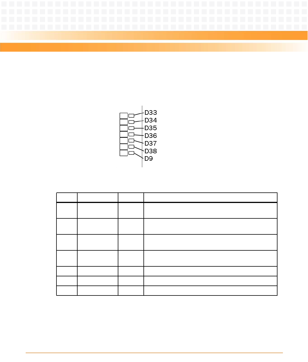
Figure 3-4 Onboard LEDs
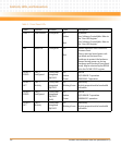
Table 3-2 Onboard LEDs Status
Label Function Color Description
D9 Power Fail Red This indicator is illuminated when one or more of the on-
board voltage rails fails.
D33 User Defined Amber Controlled by the FPGA. Used for boot-up sequence
indicator.
D34 User Defined Amber Controlled by the FPGA. Used for boot-up sequence
indicator.
D35 User Defined Amber Controlled by the FPGA. Used for boot-up sequence
indicator.
D36 Early Power Fail Amber This indicator is lit when the early 3.3V power supply fails.
D37 User Defined Amber Controlled by the FPGA
D38 User Defined Amber Controlled by the FPGA