


Controls, LEDs, and Connectors
MVME2500 Installation and Use (6806800L01H)
45
3.4.2 Onboard Connectors
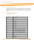
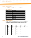
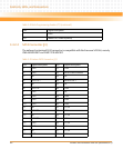
3.4.2.1 Flash Program Connector (P7)
The Flash Program Connector is depopulated in the production version of the MVME2500.
However, each pin is exposed for the 60-pin header connector for the JTAG boundary scan.
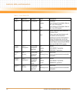
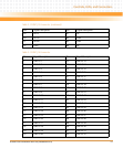
23 PMC IO 46 DATA 24 PMC IO 45 GE4_2 - Serial 3 RTS
24 PMC IO 48 DATA 25 PMC IO 47 GE4_2+ GND
25 PMC IO 50 DATA 26 PMC IO 49 GND Serial 4 RX
26 PMC IO 52 DATA 27 PMC IO 51 GE4_1 - GND
27 PMC IO 54 DATA 28 PMC IO 53 GE4_1 + Serial 4 TX
28 PMC IO 56 DATA 29 PMC IO 55 GND GND
29 PMC IO 58 DATA 30 PMC IO 57 GE4_0 - Serial 4 CTS
30 PMC IO 60 DATA 31 PMC IO 59 GE4_0 + GND
31 PMC IO 62 GND PMC IO 61 GND Serial 4 RTS
32 PMC IO 64 +5V PMC IO 63 +5V GND
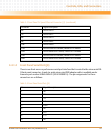
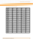
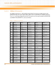
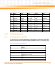
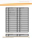
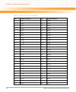
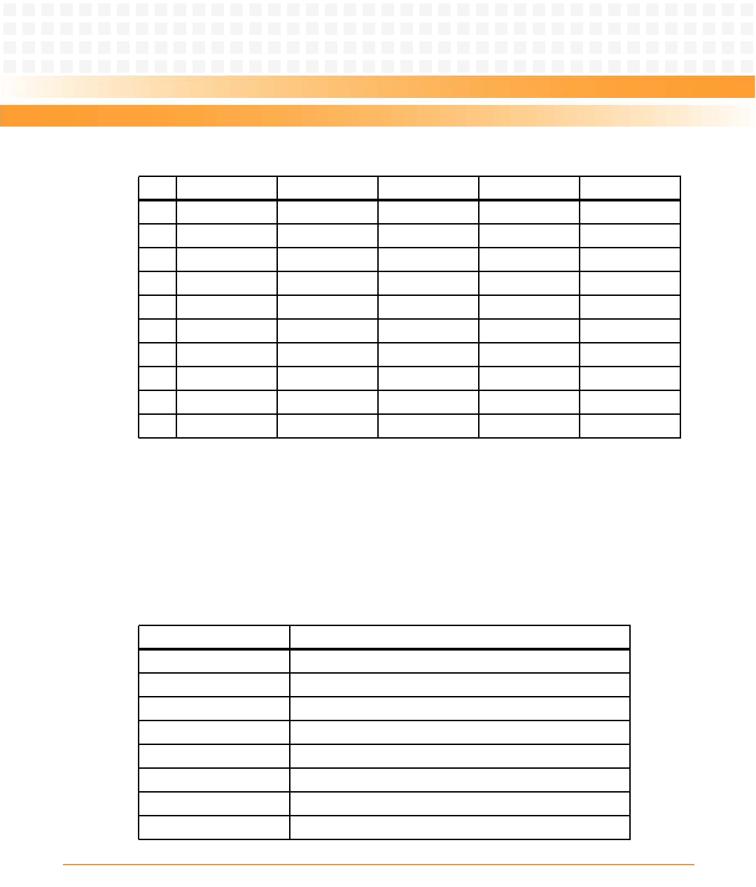
Table 3-7 VMEbus P2 Connector (continued)
Pin Row A Row B Row C Row D Row Z
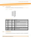
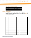
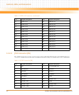
Table 3-8 Flash Programming Header (P7)
Pin Signal Description
1 HOLD 1
2 Chip Select 1
3 Chip Select 0
4 Programmer's VCC
5 Master In Slave OUT (MISO)
6 HOLD 0
7 Keying
8 CLOCK