


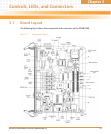
Controls, LEDs, and Connectors
MVME2500 Installation and Use (6806800L01H)
40
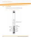
3.4.1 Front Panel Connectors
The following connectors are found on the outside of the MVME2500. These connectors are
divided between the front panel connectors and the backplane connectors. The front panel
connectors include the J1 and J5 connectors. The backplane connectors include the P1 and P2
connectors.
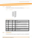
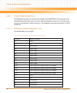
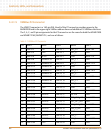
3.4.1.1 RJ45 with Integrated Magnetics (J1)
The MVME2500 uses an X2 RJ45.
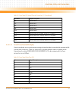
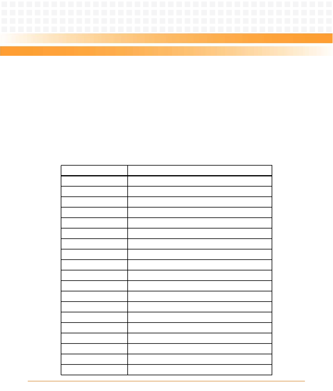
Table 3-3 Front Panel Tri-Speed Ethernet Connector (J1)
Pin Name Signal Description
1A GND
2A NC
3A Port A TRD3 -
4A Port A TRD3 +
5A Port A TRD2 -
6A Port A TRD2 +
7A Port A TRD1 -
8A Port A TRD1 +
9A Port A TRD0 -
10A Port A TRD0 +
D1A Port A Green LED1 Anode/ Yellow LED1 Cathode
D2A Port A Yellow LED1 Anode/ Green LED1 Cathode
D3A Port A Green LED2 Anode/ Yellow LED2 Cathode
D4A Port A Yellow LED2 Anode/ Green LED2 Cathode
1B GND
2B NC
3B Port B TRD3 -
4B Port B TRD3 +
5B Port B TRD2 -